SPECIFICATIONS
TORQUE SPECIFICATIONS
DESCRIPTION N·m Ft. Lbs. In. Lbs.
Axle Hub Nut 257 190 -
U-Joint Strap Bolts 38 28 -
SPECIAL TOOLS
SINGLE CARDAN UNIVERSAL
JOINTS
REMOVAL
(1) Remove the propeller shaft.
(2) Mark the yokes and propeller shaft for instal-
lation reference.
(3) Remove the bearing cap retaining clips.
CAUTION: Never clamp slip yoke tube or propeller
shaft tube in a vise. Clamp only the forged portion
of the slip yoke or propeller shaft yoke in the vise.
Do not over tighten the vise jaws.
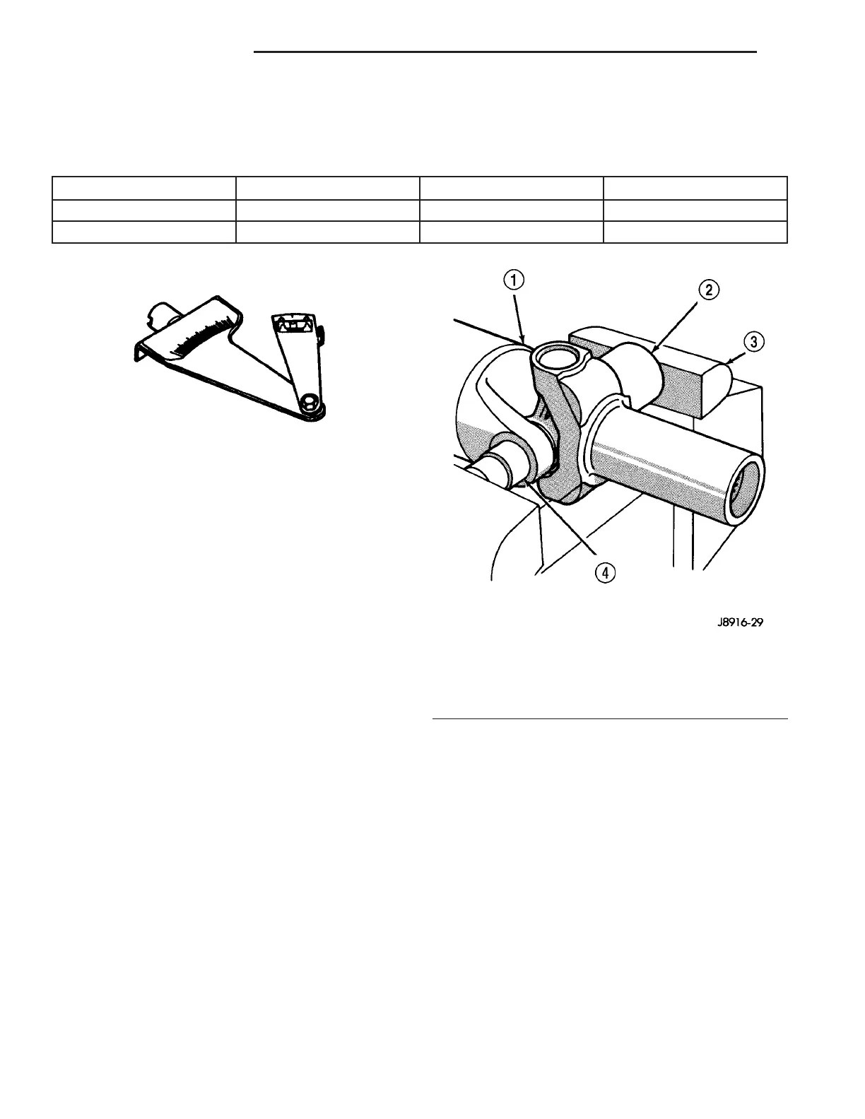
(4) Press out bearing caps with a large socket for a
reciever and a small socket as driver (Fig. 10).
(5) Tighten the vise jaws to force the bearing cap
into the larger socket (receiver).
INSTALLATION
CAUTION: Use only genuine MoparT universal
joints. Only Mopar universal joints can withstand
the high torque/impact loading this vehicle is capa-
ble of producing. The typical aftermarket u-joint is
not designed to meet the extreme impact loads
associated with this vehicle.
(1) Apply extreme pressure (EP), lithium-base
lubricant to aid in installation.
(2) Position the spider in the yoke. Insert the seals
and bearings. Tap the bearing caps into the yoke
bores far enough to hold the spider in position.
(3) Use sockets and a vise to press in bearing caps
(Fig. 11). Force the caps enough to install the retain-
ing clips.
(4) Install the bearing cap retaining clips.
(5) Install the yoke on the propeller shaft with the
reference marks aligned.
(6) Install the propeller shaft.
CAUTION: The propeller shaft strap bolts incorpo-
rate a Loctite patch. The screws must be replaced
or cleaned and Loctite thread locker applied when-
ever they are removed.
INCLINOMETER 7663
Fig. 10 BEARING CAP REMOVAL
1 - YOKE
2 - RECEIVER - LARGE SOCKET
3 - VISE
4 - DRIVER - SMALL SOCKET
3 - 6 PROPELLER SHAFT ZB
PROPELLER SHAFT (Continued)















 To Next Page