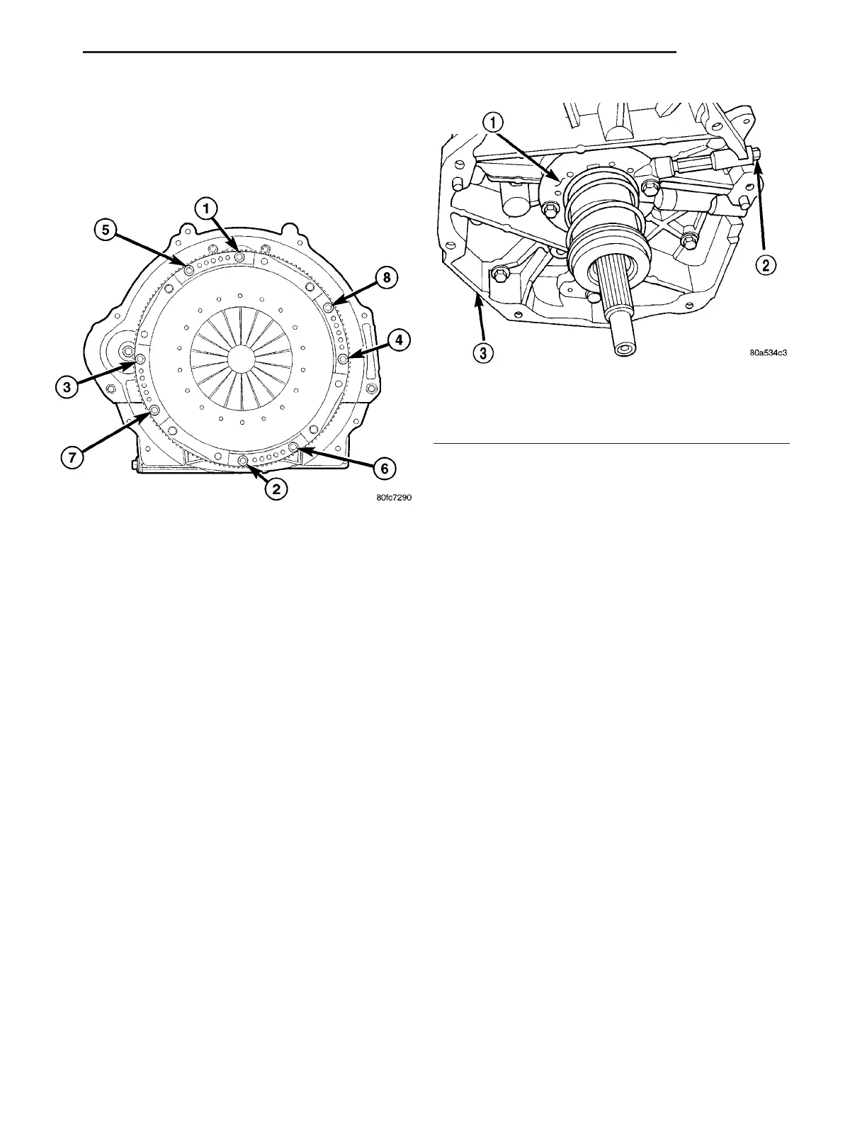
(2) To avoid distortion of the clutch cover (pressure
plate), tighten bolts a few turns at a time in
sequence (Fig. 9) until bolts are seated. Then tighten
bolts in sequence to 30 N·m (270 in. lbs.). Remove
clutch disc alignment tool.
(3) Install transmission into vehicle.
CLUTCH RELEASE BEARING
REMOVAL
NOTE: The bearing and slave cylinder are serviced
together as an assembly. Do not attempt to sepa-
rate the bearing from the slave cylinder.
(1) Raise vehicle on hoist.
(2) Disconnect hydraulic line from hydraulic slave
cylinder. Use the quick disconnect tool (special tool
6638) to open the coupling.
(3) Remove transmission assembly from the vehi-
cle.
(4) Remove slave cylinder (Fig. 10) from transmis-
sion.
INSTALLATION
(1) Install slave cylinder onto transmission.
(2) Install transmission assembly into the vehicle.
(3) Connect hydraulic line fto slave cylinder.
(4) Bleed the system.
FLYWHEEL
DIAGNOSIS AND TESTING
Common causes of flywheel problems:
• Incorrect bolt tightening
• Mounting the flywheel on a dirty crankshaft
flange
• Improper seating on the crankshaft flange shoul-
der
• Heat warpage
• Loose flywheel to crankshaft bolts
The flywheel should be replaced if warped or over-
heated. Do not machine the face of the flywheel
to correct a warped or overheated condition.
Clean the crankshaft flange and its mating surface
on the flywheel before assembling. dirt/grease in this
area could cause the flywheel to mis-align when
installing.
Use new bolts when mounting flywheel and secure
the bolts with Mopar Lock and Seal or equivalent.
Tighten flywheel bolts to specified torque only. Over
tightening can distort the flywheel causing run out.
Fig. 9 TORQUE SEQUENCE
Fig. 10 Release Bearing/Hydraulic Slave Cylinder
1 - HYDRAULIC CLUTCH RELEASE
2 - BLEED SCREW
3 - TRANSMISSION
ZB CLUTCH 6 - 9
CLUTCH DISC (Continued)