LINKAGE
DESCRIPTION
The hydraulic linkage consists of a clutch master
cylinder, reservoir, a clutch slave cylinder/release
bearing assembly and an interconnecting fluid line.
The clutch master cylinder push rod is connected
to the clutch pedal. The slave cylinder/release bear-
ing is mounted to the transmission front cover. The
clutch master cylinder is mounted on the driver side
of the dash panel adjacent to the brake master cylin-
der and booster assembly.
OPERATION
The clutch linkage uses hydraulic pressure to oper-
ate the clutch. Depressing the clutch pedal develops
fluid pressure in the clutch master cylinder. This
pressure is transmitted to the slave cylinder through
a connecting line. In turn, the slave cylinder forces
the release bearing into the pressure plate dia-
phragm spring. As additional force is applied, the
bearing presses the diaphragm spring fingers inward
on the fulcrums. This action moves the pressure
plate rearward relieving clamp force on the disc.
The slave cylinder/release bearing assembly has an
integral spring which preloads the release bearing
against the clutch diaphragm fingers to maintain
zero free-play.
MASTER CYLINDER
REMOVAL
(1) Remove master cylinder actuation rod to clutch
pedal clip.
(2) Remove anti-rotation pin from the toe box and
discard pin.
NOTE: Anti-rotation pin must not be reused.
(3)
Disconnect clutch pedal position switch connector.
(4) Remove mounting screws on clutch fluid reser-
voir.
(5) Disconnect hydraulic line quick connector
located at clutch bell housing. Use special tool 6638
to separate quick connector.
CAUTION: Do not allow brake fluid to come in con-
tact with painted surfaces of the vehicle. Paint dam-
age may occur.
(6) Remove left inner fender for access to the mas-
ter cylinder.
(7) Twist clutch master cylinder a quarter turn
counterclockwise to remove from toe box.
(8) Remove assembly from vehicle.
INSTALLATION
(1) Twist clutch master cylinder a quarter turn
clockwise to install into toe box.
(2) Connect hydraulic line quick connector to
clutch bell housing.
(3) Install clutch fluid reservoir mounting screws.
(4) Install left inner fender.
(5) Connect clutch pedal position switch connector.
(6) Install new anti-rotation pin.
(7) Install master cylinder actuation rod to clutch
pedal clip.
(8) Bleed system.
CLUTCH PEDAL POSITION
SWITCH
DESCRIPTION
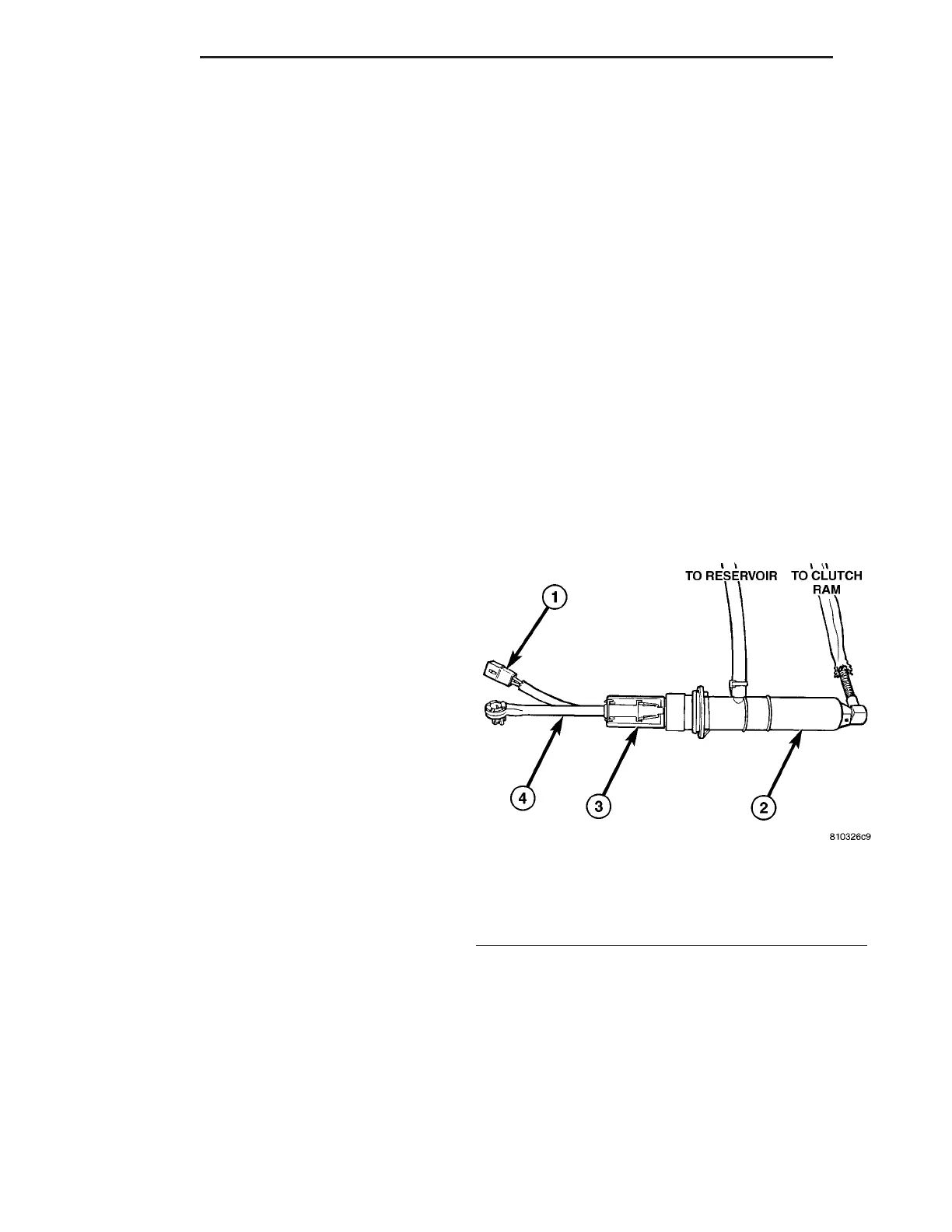
The clutch pedal position switch is located on the
clutch master cylinder actuation rod (Fig. 11). The
switch is held in place by a plastic retaining clip. The
clutch master cylinder must be removed to replace
this switch.
OPERATION
The function of the clutch pedal position switch is
to prevent the engine starter from operating until the
clutch pedal is depressed. This switch will prevent
accidental engagement of starter while vehicle is in
gear.
Fig. 11 CLUTCH SWITCH LOCATION
1 - CLUTCH POSITION SWITCH CONNECTOR
2 - HYDRAULIC CLUTCH MASTER CYLINDER
3 - CLUTCH POSITION SWITCH
4 - CLUTCH ACTUATION ROD
6 - 10 CLUTCH ZB










 To Next Page