(5) Attach a socket to the vibration damper mount-
ing bolt and rotate engine until the 1–15/32 inch
dimension is attained.
(6) Install the sensor into the timing case/cover
with a slight rocking action until the sensor is
aligned to scribe line. The paper spacer can be used
if reinstalling a used sensor.
(7) Install sensor mounting bolt and tighten to
10.7 N·m (95 in. lbs.) torque.
(8) Connect engine wiring harness to sensor.
IGNITION COIL
OPERATION
The Auto Shutdown (ASD) relay provides battery
voltage to the ignition coil. The PCM provides a
ground contact (circuit) for energizing the coil. When
the PCM breaks the contact, the energy in the coil
primary transfers to the secondary causing the
spark. The PCM will de-energize the ASD relay if it
does not receive the crankshaft position sensor and
camshaft position sensor inputs
REMOVAL
(1) Release the fuel pressure, refer to the Fuel
Pressure Release procedure in the Fuel Section.
(2) Disconnect the negative battery cable.
(3) Remove the air cleaner assembly, refer to the
Engine/Air Intake section for more information.
(4) Remove the Intake Manifold, refer to the
Engine/Manifolds/Intake Manifold for more informa-
tion.
(5) Unlock and disconnect the electrical connector
at the ignition coils (Fig. 7) and (Fig. 8).
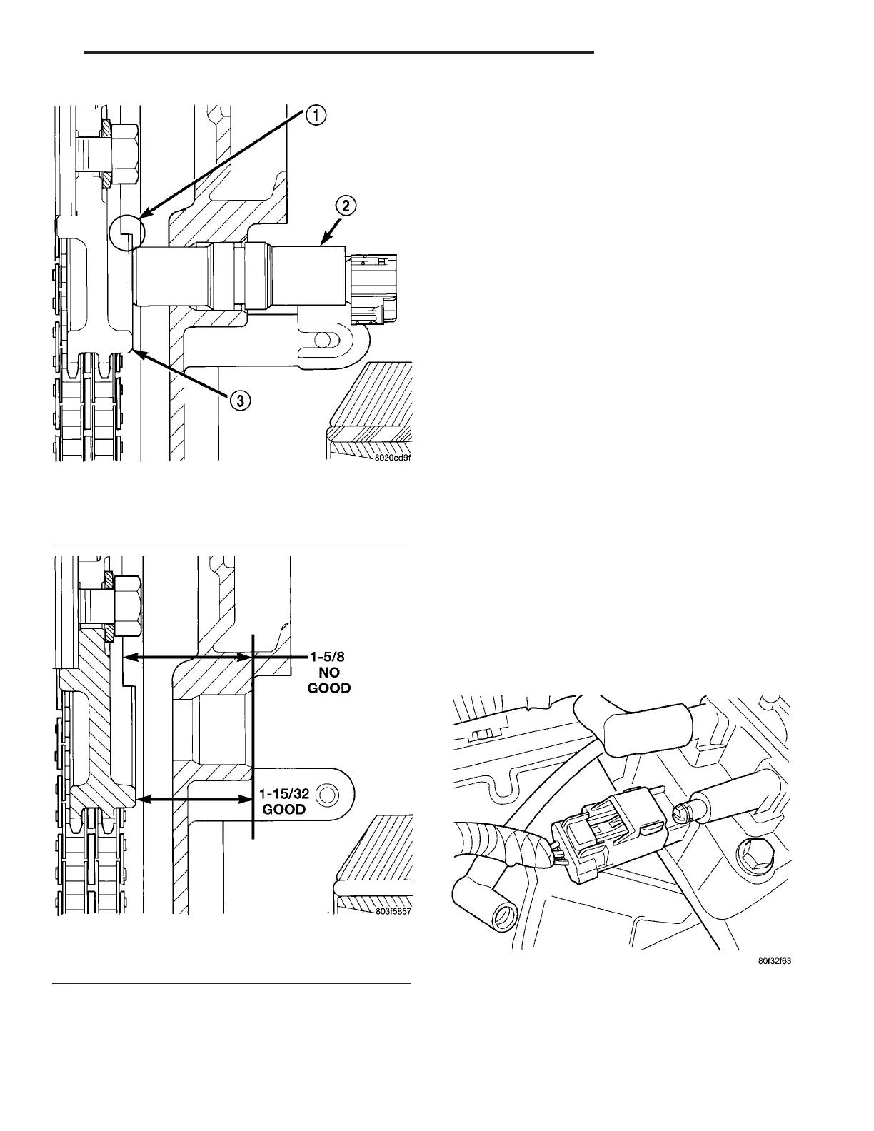
Fig. 5 Sensor Operation
1 - MACHINED STEP
2 - CAMSHAFT POSITION SENSOR
3 - CAM DRIVE GEAR
Fig. 6 Sensor Depth Dimensions
1 - 1-5/8 inches NO GOOD
2 - 1-15/32 inches GOOD
Fig. 7 FRONT COIL ELECTRICAL CONNECTOR
ZB IGNITION CONTROL 8I - 5
CAMSHAFT POSITION SENSOR (Continued)