INSTALLATION
(1) Insert cable assembly through opening in dash
panel (Fig. 24). Seat cable retainer in dash panel.
(2) From inside the vehicle, hold up the pedal and
install the throttle cable and cable retainer in the
upper end of the pedal shaft (Fig. 23).
(3) Connect the throttle cable to the throttle body
(Fig. 22).
THROTTLE POSITION SENSOR
DESCRIPTION
The TPS is mounted on the passenger side of the
throttle body. The sensor connects to the throttle
blade shaft (Fig. 25). The TPS is a variable resistor
that provides the Powertrain Control Module (PCM)
with an input signal (voltage).
OPERATION
The TPS is a variable resistor that provides the
PCM with an input signal (voltage). The signal rep-
resents throttle blade position. As the position of the
throttle blade changes, the resistance of the TPS
changes.
The PCM supplies approximately 5 volts to the
TPS. The TPS output voltage (input signal to the
PCM) represents throttle blade position. The TPS
output voltage to the PCM varies from approximately
0.5 volt at minimum throttle opening (idle) to 3.5
volts at wide open throttle. Along with inputs from
other sensors, the PCM uses the TPS input to deter-
mine current engine operating conditions. The PCM
also adjusts fuel injector pulse width and ignition
timing based on these inputs.
REMOVAL
The TPS is attached to the throttle body (Fig. 25).
(1) Disconnect the TPS electrical connector.
(2) Remove the TPS mounting screws.
(3) Remove the TPS.
Fig. 24 THROTTLE CABLE ROUTING
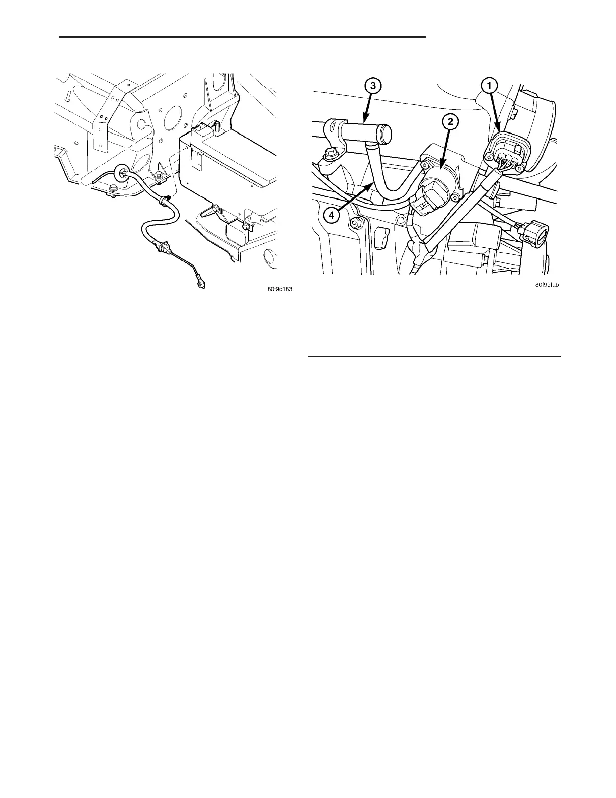
Fig. 25 TPS & IDLE AIR CONTROL
1 - Throttle Position Sensor
2 - Idle Air Control Motor
3 - Fuel Rail
4 - Connector Fuel Line for Fuel Rails
ZB FUEL INJECTION 14 - 41
THROTTLE CABLE (Continued)
 Loading...


