56
ED100LE 02-2021DL4616-001
dormakaba ED100 low energy operator – Fine cover
Installation Instructions
Appendix A
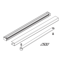
Fig. A.1.8 Program switch kit
4 Program switch kit
HC3482-010
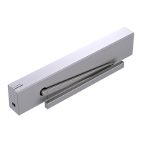
A.. Install program switches.
. Install program switch assembly; slide
program switch board into cover bracket
slot.
A.. Secure program switch cable.
. Place program switch cable in mounting
plate groove and secure with . x "
wire retainers.
. Coil any remaining cable and secure to
mounting plate with cable ties.
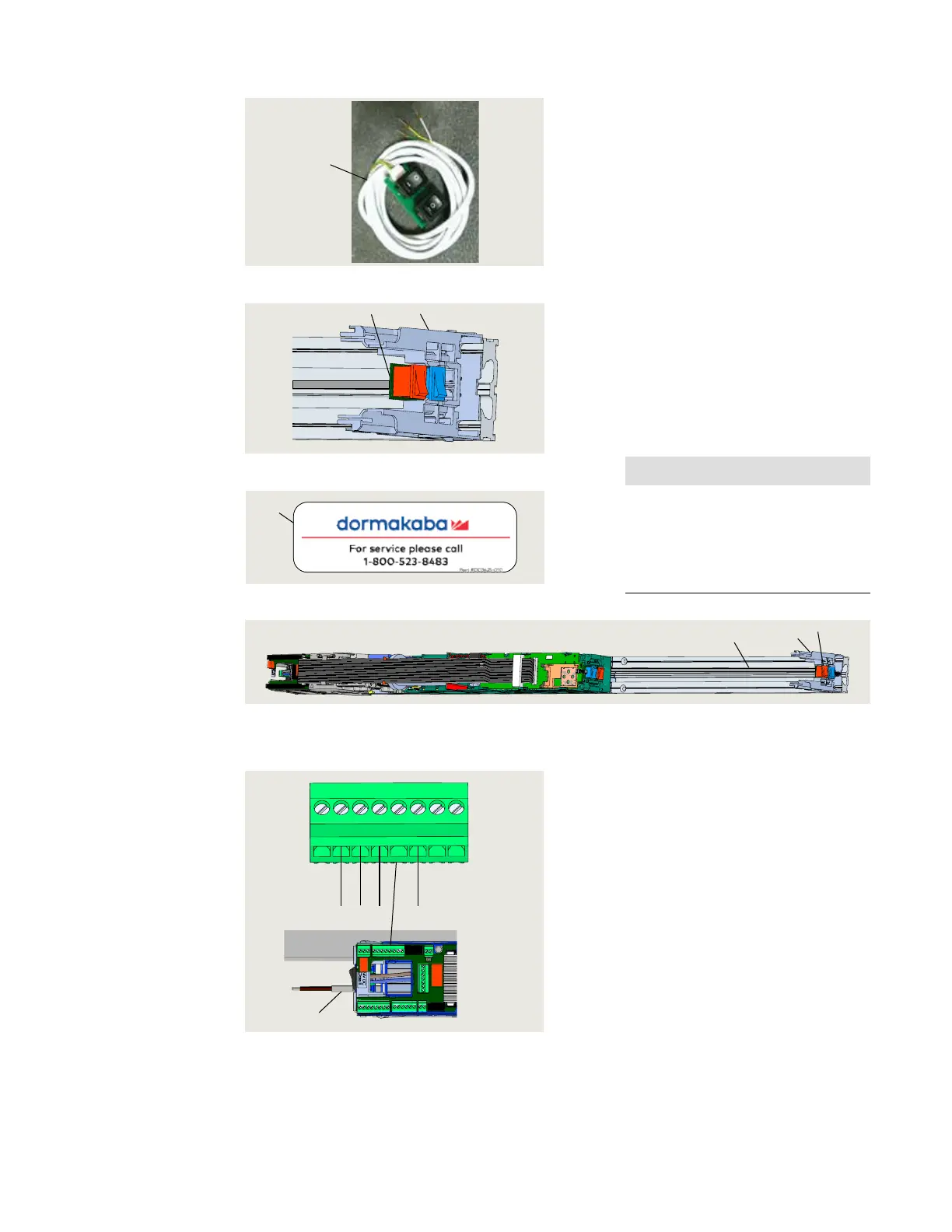
A.. Install Service Call label in cover.
. Install Service Call label on inside of
cover.
• Service call label included in Low Energy
label kit HK3137-010.
A.. Return to installation chapter.
. Return to Para. ., Mounting plate
attachment to jamb or wall.
NOTICE
Program switch wiring.
Once ED100LE operator is
installed, program switch wires will
be connected to terminal board
(Fig. A.1.10).
Fig. A.1.11 ED100LE installation with mounting plate extension
Fig. A.1.12 ED100LE program switch wiring
3 Professional cover
bracket
HC3481-010
4 Program switch kit
HC3482-010
4
Fig. A.1.9 Program switch installation
4
3
3 Professional cover
bracket
HC3481-010
4 Program switch kit
HC3482-010
4.1 Program switch
cable
3
4
4.1
30
31
32 33
34
3
35
3
Brown
Green
White
X1
4.1
Yellow
4.1 Program switch
cable
1 Label, Service call,
DD3425-010
1
Fig. A.1.10 Label, service call