20
WN 059677 45532 - 11/2023
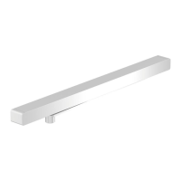
ES 250 PRO/ES 250 PRO FST
ES 400 PRO/ES 400 PRO FST
Mounting instructions
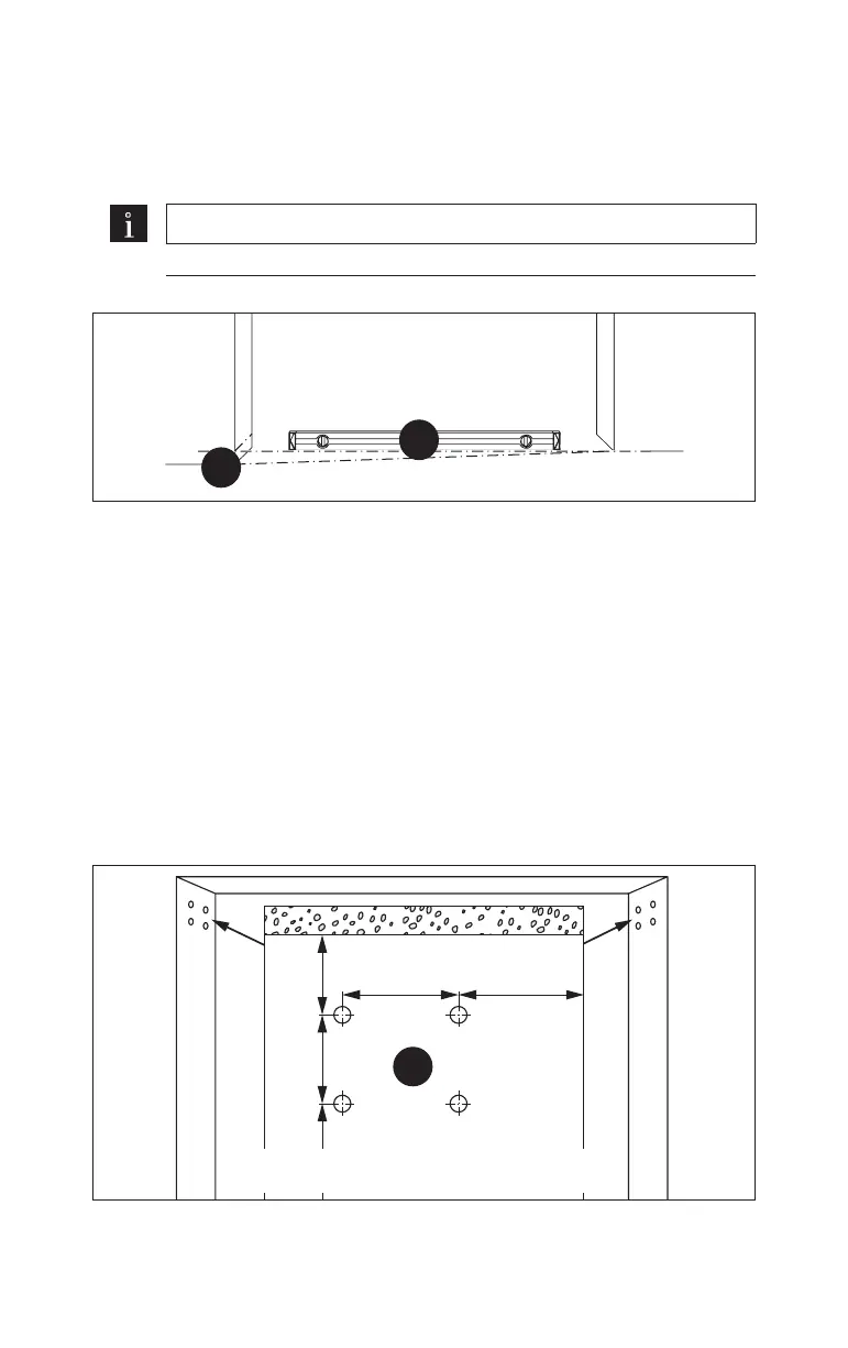
4.3.4 Mount the operator profile in the passage
1. Determine the highest point of the floor in the leaves’ area of travel.
Note
Use a leveling device.
Fig.19
2.
1.
2. Transfer the highest point of the floor to the wall.
3. The clear height (CH) can be found in the planning documents.
4. Mark and drill the two lower holes on the left side. Mark and drill the two
upper holes on the right side:
if the internal cover with a height of 100mm is being used, the distance from
the floor to the center of the lower drill hole on the wall mounting
=CH+28mm.
If the internal cover with a height of 150mm is being used, the distance from
the floor to the center of the lower drill hole on the wall mounting
=CH+78mm.
The clear height must be adhered to.
Fig.20
4.
55
min. 5042X
min. 78
outsideinside
 Loading...