49
WN 059677 45532 - 11/2023
ES 250 PRO/ES 250 PRO FST
ES 400 PRO/ES 400 PRO FST
Mounting instructions
5.2 Properties of CANBUS systems
• The CANBUS is a 4-wire bus, comprising +24V, GND and 2data cables (CAN-L
and CAN-H).
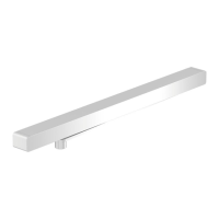
• Because the connectors on the CAN BUS cables are very small, a housing is
sometimes mounted on the connectors. The housing makes it easier to connect
the connectors in hard-to-reach places.
Fig.79
• The CANBUS components are automatically detected by the control unit.
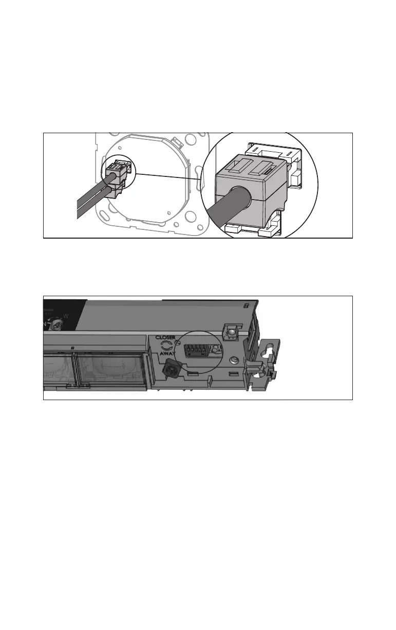
• The function (combined function/safety secondary closing edge) and position
(inside/outside) of the sensors must be set (DIP switches1-4).
Fig.80
• If a CANBUS component is replaced or removed from the network, a CAN BUS
reset must be carried out.