54
WN 059677 45532 - 11/2023
ES 250 PRO/ES 250 PRO FST
ES 400 PRO/ES 400 PRO FST
Mounting instructions
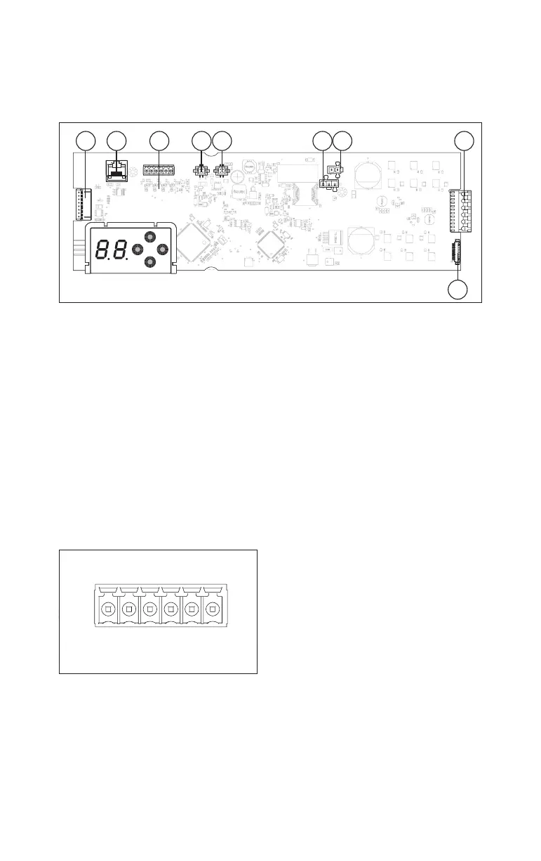
6 Terminal layout
6.1 Terminal layout of the control board
Fig.87
1 2 3 4 5 6 7 8
9
(1) Operator locking device connection
(2) RS232 connection
(3) Multiport Fig.88
(4) CAN BUS port 1
(5) CAN BUS port 2
(6) Power supply connection
(7) Battery pack connection
(8) Drive connection
(9) Hall effect sensor connection
6.2 Multiports
The multiports are used to connect components that are not CAN BUS-compatible
to the control unit.
There are 3 pre-installed configurations, which are sufficient for most application
scenarios.
If the pre-installed configurations are not sufficient, the multiports can be
configured individually via the OSI as an input (high-/low-active, normally open/
normally closed) or as an output (open collector).
Fig.88
1
3
io1
io2
io3
io4
Terminal Connection
1 + 24V
3 GND (ground)
I/O 1 Multiport 1
I/O 2 Multiport 2
I/O 3 Multiport 3
I/O 4 Multiport 4 and Wake-Up*
* In battery mode, the control unit switches to energy-saving mode. The control
unit can only be activated via multiport 4.