52
WN 059677 45532 - 11/2023
ES 250 PRO/ES 250 PRO FST
ES 400 PRO/ES 400 PRO FST
Mounting instructions
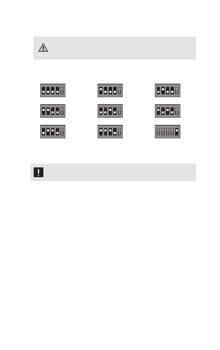
5.2.4 DIP switches on the sensors
Warning
For escape route sliding doors, a combination detector must always
be connected to the inside of the MCE with the DIP switch position
MCEinside1!
The various addresses (function/position) are set on the DIP switches 1-4. The
terminating resistor is activated on DIP switch 5.
ON
12
345
DIPON
12
345
DIPON
12
345
DIP
ON
12
345
DIPON
12
345
DIPON
12
345
DIP
ON
12
345
DIPON
12
345
DIP
ON
12
345
DIP
ON
12
345
DIPON
12
345
DIPON
12
345
DIP
ON
12
345
DIPON
12
345
DIPON
12
345
DIP
ON
12
345
DIP
ON
12
345
DIP
ON
12
345
DIPON
12
345
DIPON
12
345
DIP
ON
12
345
DIPON
12
345
DIPON
12
345
DIP
ON
12
345
DIP
MCE inside 1 MCE inside 2 MCE inside 3
ON
12
345
DIPON
12
345
DIPON
12
345
DIP
ON
12
345
DIPON
12
345
DIP
ON
12
345
DIP
ON
12
345
DIPON
12
345
DIPON
12
345
DIP
ON
12
345
DIPON
12
345
DIPON
12
345
DIP
ON
12
345
DIP
ON
12
345
DIP
ON
12
345
DIP
ON
12
345
DIPON
12
345
DIPON
12
345
DIP
ON
12
345
DIPON
12
345
DIPON
12
345
DIP
ON
12
345
DIP
ON
12
345
DIPON
12
345
DIP
ON
12
345
DIPON
12
345
DIPON
12
345
DIP
MCE outside 1 MCE outside 2 MCE outside 2
ON
12
345
DIP
ON
12
345
DIPON
12
345
DIPON
12
345
DIP
ON
12
345
DIPON
12
345
DIPON
12
345
DIP
ON
12
345
DIP
ON
12
345
DIP
ON
12
345
DIPON
12
345
DIPON
12
345
DIP
ON
12
345
DIPON
12
345
DIPON
12
345
DIP
ON
12
345
DIP
ON
12
345
DIPON
12
345
DIP
ON
12
345
DIPON
12
345
DIPON
12
345
DIP
ON
12
345
DIPON
12
345
DIPON
12
345
DIP
SCE 1 SCE 2 Terminating resistor
is activated
5.3 Structure of a CANBUS system
Attention
The CANBUS components must not be connected under live voltage!
1. Remove the terminating resistor from the required CANBUS connections on
the operator control unit and retain.
2. Connect the CANBUS components in any order to the CANBUS cables.
3. Drill the holes for carrying out the CAN BUS cable with 8mm and then
deburr.
4. Clean the operator profile and running profile.
5. In both CANBUS components furthest away from the control unit, measured
by cable length, connect 1 terminating resistor or activate the switchable
terminating resistor (sensors).