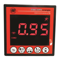
5.2 RS485 serial connection
For the models featuring the RS485 serial port, connect the signal as indicated in the figure below, taking into
account that the positive signal must be connected to pin A and the negative signal to pin B.
By short-circuiting pin B across pin T, the line can be terminated with a 120 Ohm resistance, already present inside
the electronics.
For detailed information on protocol, address and baud rate parameter settings, refer to Chap. 7.4 - Communication
interface settings.
For detailed information on Modbus-RTU and ASCII Ducbus protocol specifications, refer to the documents available
at the following link: ftp://ftp.ducatienergia.com/DucatiSistemi/Protocols_Analysers/
GO BACK TO CONNECTIONS
GO BACK TO CONTENTS
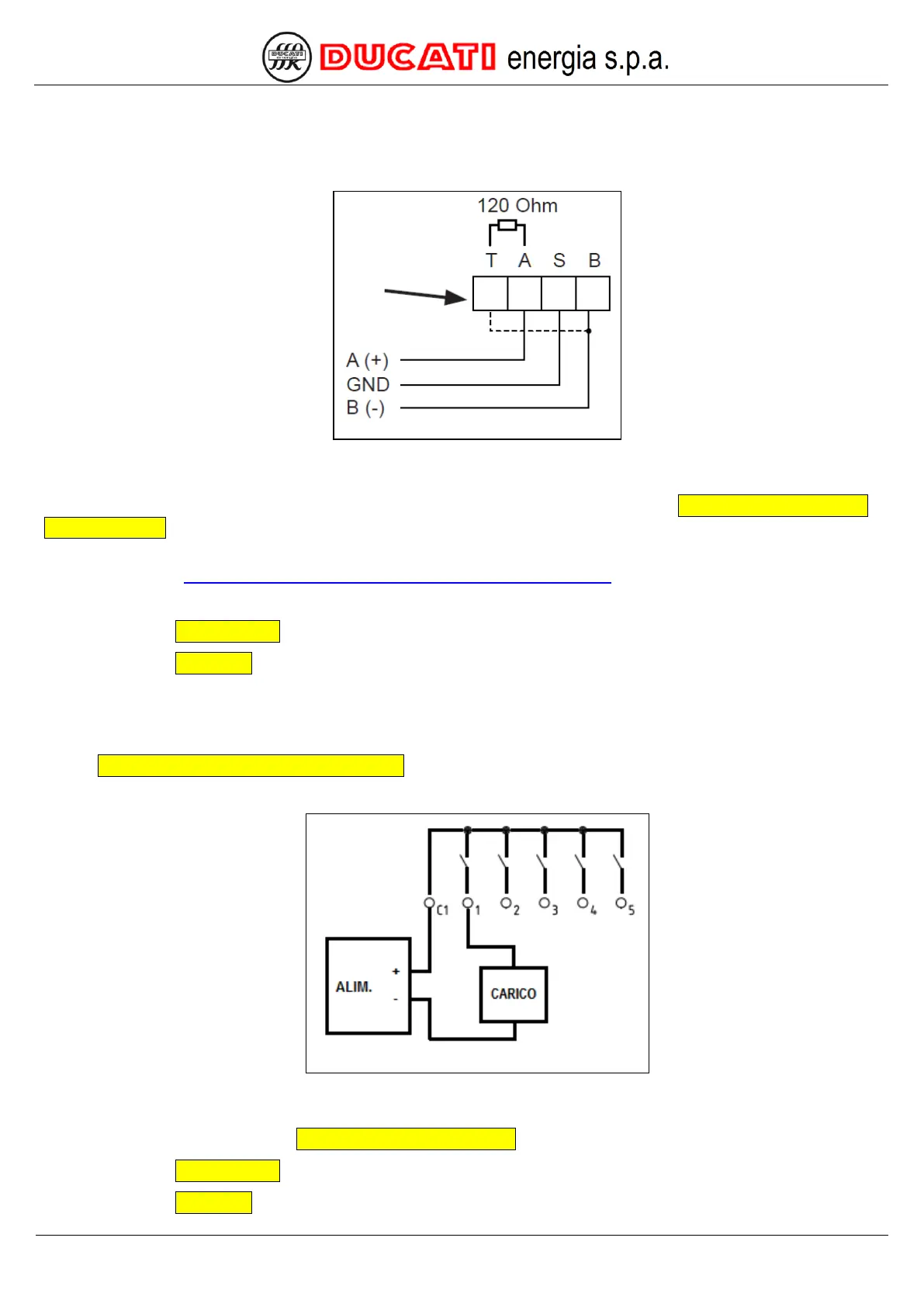
5.3 Output alarm connection
Relay outputs can be connected as alarm outputs. For detailed information on how to configure an output as alarm,
refer to Chap. 7.3 - Power factor correction settings.
The figure below shows how to connect output 1.
The contact is in NO (normally open) logic, and it closes if the output-associated alarm is activated.
The power supply unit (PWR) and the reading electronics (LOAD) must comply with the indications provided in the
technical features of relay outputs in Chap. 3 - TECHNICAL FEATURES.
GO BACK TO CONNECTIONS
GO BACK TO CONTENTS