MANAGEMENT
The activation of the power factor correction failed alarm will not affect the status of the inserted banks.
The relay outputs set as "ALA" and associated to the "LOcosphi" or "ALL" alarm will be activated unless parameter
P.25 – Alarm masking management (Chap. 7.6) has been set to mask the alarms under defined operating conditions.
DISPLAYING
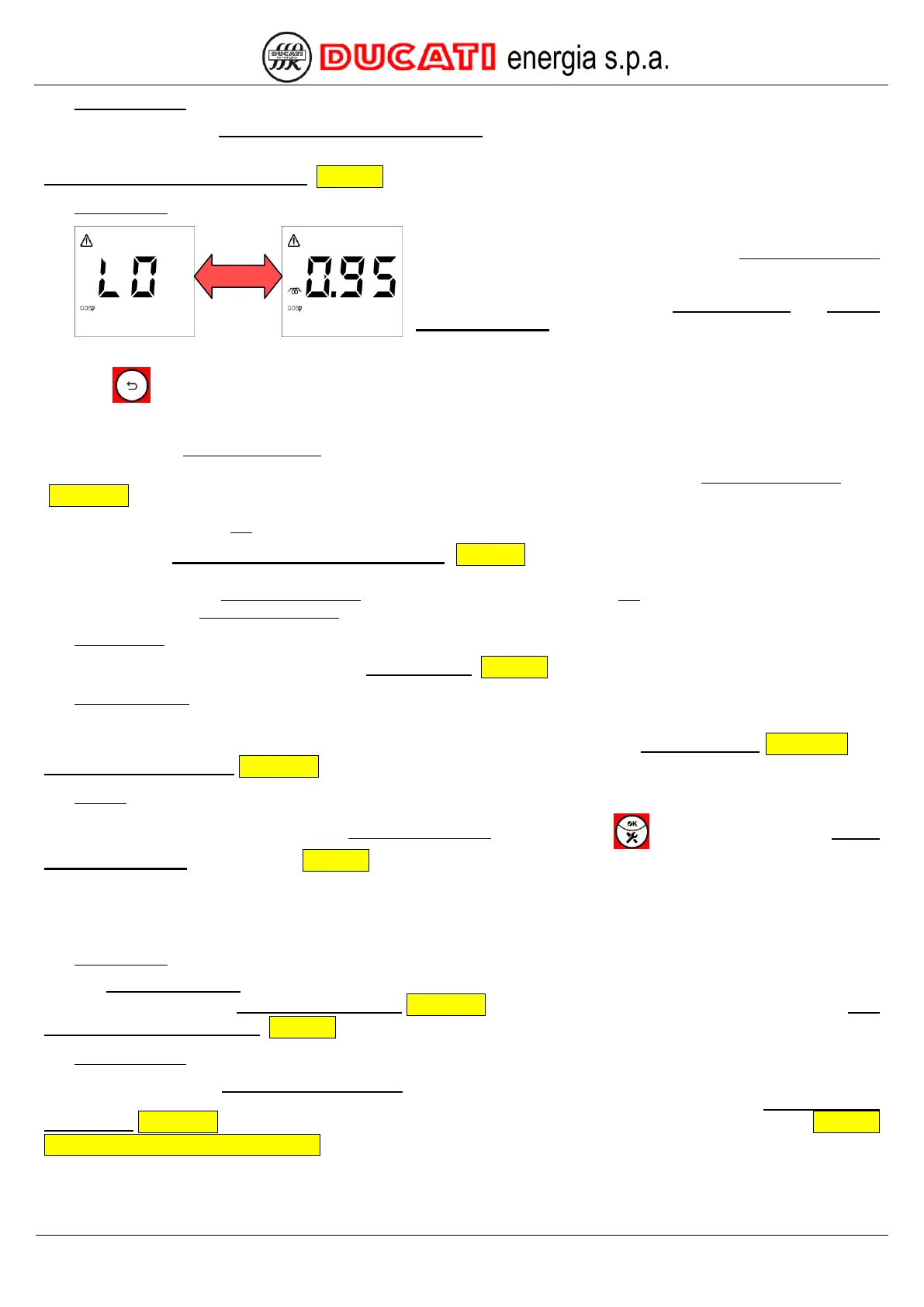
Regardless of the current displaying, the alarm will be indicated
with the displaying of the relevant page of the Current alarm menu
that will be alternately shown with the numerical value
corresponding to the most inductive extreme value of the target
cosphi range defined by parameters Cosphi setpoint and Cosphi
setpoint tolerance (0.95 inductive in the example shown).
The Controller will stay in the above-mentioned screen until:
- key is pressed for more than 2sec (the alarm is anyway active);
- alarm is deactivated or manually reset by the operator.
Afterwards, the Measurement Menu will be automatically displayed and will show, respectively:
- the cosphi value and the alarm icon on the top left. The alarm will be anyway active in the Current Alarm Menu
(Chap. 8.5.1);
- the cosphi value, but not the alarm icon.
If, parameter P.25 – Alarm masking management (Chap. 7.6) has been set to mask the alarms under defined
operating conditions, the previous screen will be temporarily displayed for 3sec. The alarm will then automatically go back
to the first screen of the Measurement Menu by displaying the cosphi value, but not the alarm icon. The alarm will be
anyway present in the Current Alarm Menu.
STATISTICS
The alarm counter will be increased in the Statistics Menu (Chap. 8.4) at every occurrence.
DEACTIVATION
The alarm is automatically deactivated as soon as the cosphi value goes above the numerical value corresponding to
the most inductive extreme value of the target cosphi range defined by parameters Cosphi setpoint Chap. 7.3.1 and
Cosphi setpoint tolerance Chap. 7.3.2.
RESET
Alarm can be manually reset from the Current Alarm Menu by pressing key (function possible only if P.13 –
Current alarm reset = “ON”, refer to Chap. 7.6).
8.5.2.10 Micro-interruption alarm
ACTIVATION
The micro-interruption alarm is activated if the voltmetric input of the R5 Controller stays below 10% of the nominal
value defined by parameter VT secondary winding Chap. 7.1.8 for a time (in msec) equal to the value of parameter P.20
– Micro-interruption duration (Chap. 7.6).
MANAGEMENT
The activation of the micro-interruption alarm triggers the immediate and simultaneous disconnection of all banks.
This process takes place in automatic power factor correction mode for all the inserted banks whose Step n function
(n=1,2,3,4,5) Chap. 7.2.5 has been set to “CAP” or “ON” and in manual power factor correction mode (refer to Chap. 8.8
- Manual power factor correction mode) for all the banks whose status has been set to "ON".