Example 1: if CT primary winding = “5”, the possible settable values are [6.00; 5.95; 5.90; 5.85; 5.80; 5.75; 5.70;
5.65; 5.60; 5.55; 5.50; 5.45; 5.40; 5.35; 5.30; 5.25; 5.20; 5.15; 5.10; 5.05; 5.00; 4.95; 4.90; 4.85; 4.80; 4.75; 4.70; 4.65;
4.60; 4.55; 4.50; OFF).
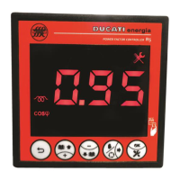
Example 2: if CT primary winding = “5.00k” and you wish to set the threshold at 105% (5.25kA), scroll the
suggested values and set:
Example 3: to disable the alarm set:
After parameter is confirmed, the controller will move to the next parameter setting screen (Overcurrent alarm
delay).
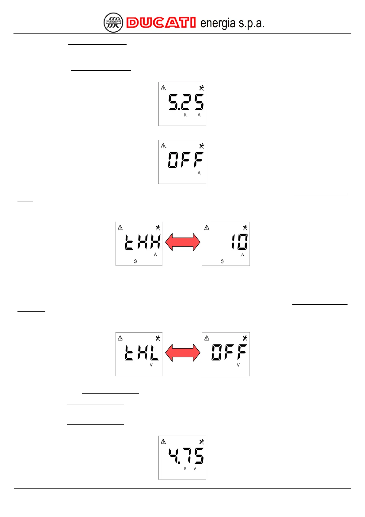
7.5.4 Overcurrent alarm delay
The default value is "10". The permitted range for the parameter is [1÷255] seconds.
NOTE: the alarm will be activated and deactivated if the reference measurement steadily stays above or under the
threshold for the time set.
If a permitted value is entered, the controller will move to the next parameter setting screen (Low voltage alarm
threshold).
7.5.5 Low voltage alarm threshold
The default value is "OFF". The possible permitted values for the parameter will range from 90% to 110% of the
value set for parameter VT primary winding with a 1% resolution. To disable the alarm select the "OFF" value.
Example 1: if VT primary winding = “400”, the possible settable values are [440; 436; 432; 428; 424; 420; 416; 412;
408; 404; 400; 396; 392; 388; 384; 380; 376; 372; 368; 364; 360; OFF].
Example 2: if VT primary winding = “5.00k” and you wish to set the threshold at 95% (4.75kV), scroll the suggested
values and set: