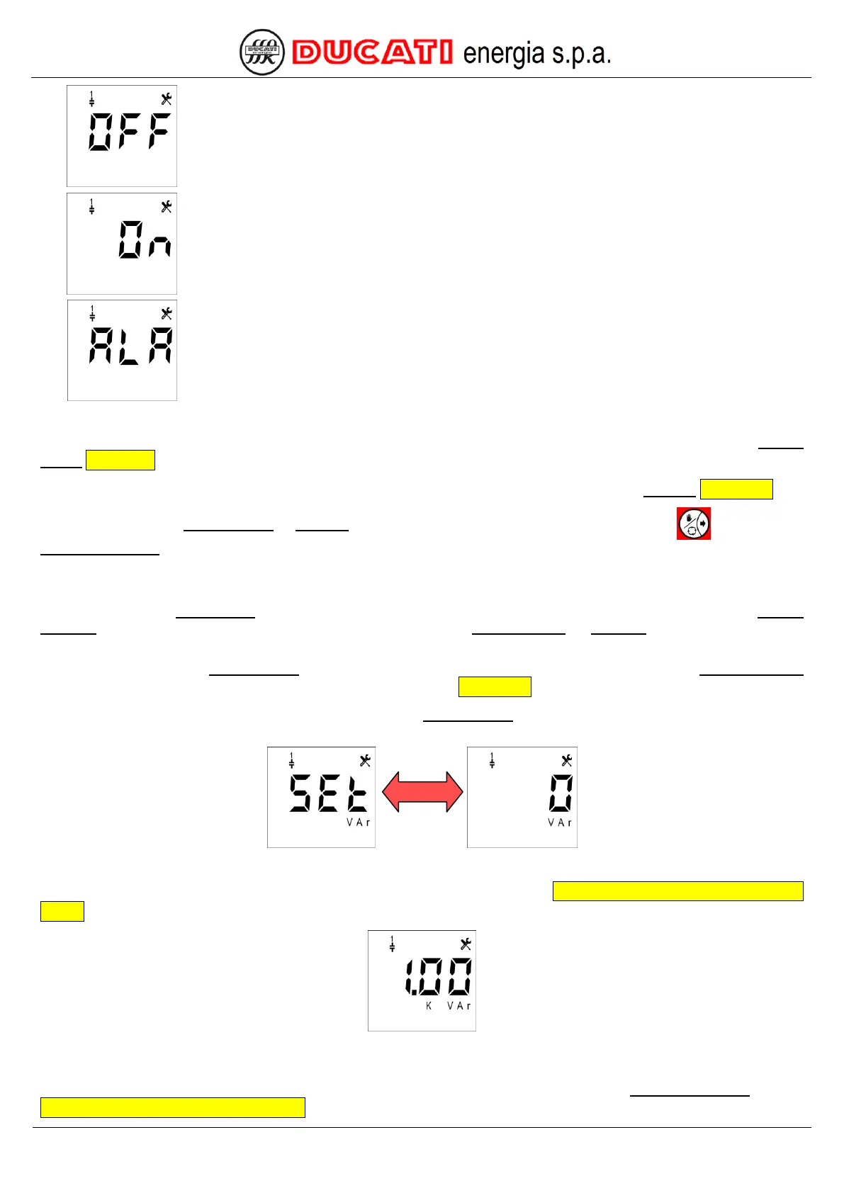
Select the "OFF" value for an output not connected or connected to a bank that you do not
want to use.
Select the "ON" value for an output connected to a bank that you want to keep always on.
Select the "ALA" value for an output used as alarm contact.
The controller will move to different screens based on the selection made:
- if "CAP", "OFF" or "ON" value has been set, the controller will move to the setting screen of parameter Step n
power Chap.7.2.6;
- if the "ALA" value has been set, the controller will move to the setting screen of parameter Alarm n Chap. 7.2.7.
By confirming the Step n power or Alarm n parameter or by scrolling the Setup Menu with key the parameter
Step n+1 function will be displayed, and so on until index n = 5.
7.2.6 Step n power (n=1,2,3,4,5)
By scrolling the Setup Menu for each relay output (1 to 5) there are a first page for function definition (Step n
function) and a second page for further parameter specification (Step n power or Alarm n) based on the selected
function.
NOTE: the parameter Step n power is displayed only for the relay outputs for which the parameter Step n function
has been set to “CAP”, “OFF” or “ON”. For further details, refer to Chap. 7.2.5.
NOTE: the images and the description below show the Step 1 power parameter, i.e. all what can be applied for all
steps with n index with n = 1,2,3,4,5.
The default value is "0". The permitted range for the parameter is [0÷999]kVar.
Example: to set 1kVar, enter (for numerical value entering mode refer to Chap. 7.8 - Numerical value entering
modes):
If the controller is installed on a Ducati energia power factor correction equipment, the value to be entered is the one
specified on equipment plate.
If a permitted value is entered, the controller will move to the setting screen of parameter Step n+1 function (refer to
Chap. 7.2.5 - Step n function (n=1,2,3,4,5)).