8.5 Alarm management and display
8.5.1 Current alarm menu
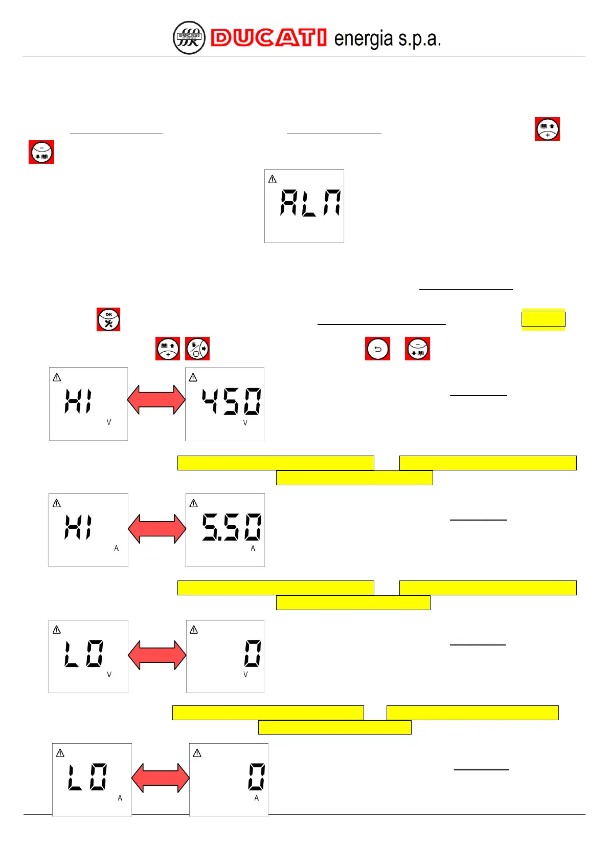
The Current Alarm Menu can be accessed from the Measurement Menu by simultaneously pressing keys and
for more than 2sec. The controller will display the following screen:
Menu can be accessed only if there is at least one current alarm, otherwise pressing the previous keys will not have
any effect.
NOTE: no page will be available for non-active alarms, but all the pages of the Current Alarm Menu are described
hereinafter in the correct displaying sequence as if all alarms were simultaneously active.
Press key to reset the alarm (function possible only if P.13 – Current alarm reset = “ON”, refer to Chap. 7.6).
Now press one of keys , to scroll the pages or one of keys or
to scroll pages back.
The next displayed page relates to the overvoltage alarm that will
be alternately shown with the numerical value corresponding to the
maximum voltage value measured since alarm activation (450V in
the example shown).
For alarm settings, refer to Chap. 7.5.1 - Overvoltage alarm threshold and Chap. 7.5.2 - Overvoltage alarm delay.
For further information on alarm management, refer to Chap. 8.5.2.1 - Overvoltage alarm.
The next displayed page relates to the overcurrent alarm that will
be alternately shown with the numerical value corresponding to the
maximum current value measured since alarm activation (5.5A in
the example shown).
For alarm settings, refer to Chap. 7.5.3 - Overcurrent alarm threshold and Chap. 7.5.4 - Overcurrent alarm delay.
For further information on alarm management, refer to Chap. 8.5.2.2 - Overcurrent alarm.
The next displayed page relates to the low voltage alarm that will
be alternately shown with the numerical value corresponding to the
minimum voltage value measured since alarm activation (0V in the
example shown).
For alarm settings, refer to Chap. 7.5.5 - Low voltage alarm threshold and Chap. 7.5.6 - Low voltage alarm delay. For
further information on alarm management, refer to Chap. 8.5.2.3 - Low voltage alarm.
The next displayed page relates to the low current alarm that will
be alternately shown with the numerical value corresponding to
the minimum current value measured since alarm activation (0A in
the example shown).