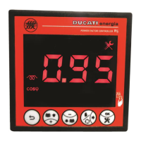
DISPLAYING
Regardless of the current displaying, the alarm will be indicated
with the displaying of the relevant page of the Current alarm menu
that will be alternately shown with the numerical value
corresponding to alarm activations.
The Controller will stay in the above-mentioned screen until:
- key is pressed for more than 2sec (the alarm is anyway active);
- alarm is deactivated.
Afterwards, the Measurement Menu will be automatically displayed and will show, respectively:
- the cosphi value and the alarm icon on the top left. The alarm will be anyway active in the Current Alarm Menu
(Chap. 8.5.1);
- the cosphi value, but not the alarm icon.
If, parameter P.25 – Alarm masking management (Chap. 7.6) has been set to mask the alarms under defined
operating conditions, the previous screen will be temporarily displayed for 3sec. The alarm will then automatically go back
to the first screen of the Measurement Menu by displaying the cosphi value, but not the alarm icon. The alarm will be
anyway present in the Current Alarm Menu.
STATISTICS
The alarm counter will be increased in the Statistics Menu (Chap. 8.4) at each occurrence not causing the complete
powering-off of the R5 Controller.
DEACTIVATION
The alarm is automatically deactivated after a time equal to the Re-connection time Chap.7.2.3.
RESET
This alarm cannot be manually reset from the Current Alarm Menu.
8.5.2.11 Bank n breakage alarm (n=1,2,3,4,5)
ACTIVATION
The alarm bank n breakage (n=1,2,3,4,5) is activated if bank n estimated reactive power decreases by a percentage
equal to or higher than P.10 – Fault threshold 1 (if P.8 – Presence of blocking reactors = “OFF”) or P.12 – Fault
threshold 2 (if P.8 – Presence of blocking reactors = “ON”). For further details, refer to (Chap. 7.6).
MANAGEMENT
The activation of bank n breakage alarm (n=1,2,3,4,5) triggers the immediate disconnection of bank n. This process
takes place in automatic power factor correction mode for all the inserted banks whose Step n function (n=1,2,3,4,5)
Chap. 7.2.5 has been set to “CAP” or “ON” and in manual power factor correction mode (refer to Chap. 8.8 - Manual
power factor correction mode) for all the banks whose status has been set to "ON".
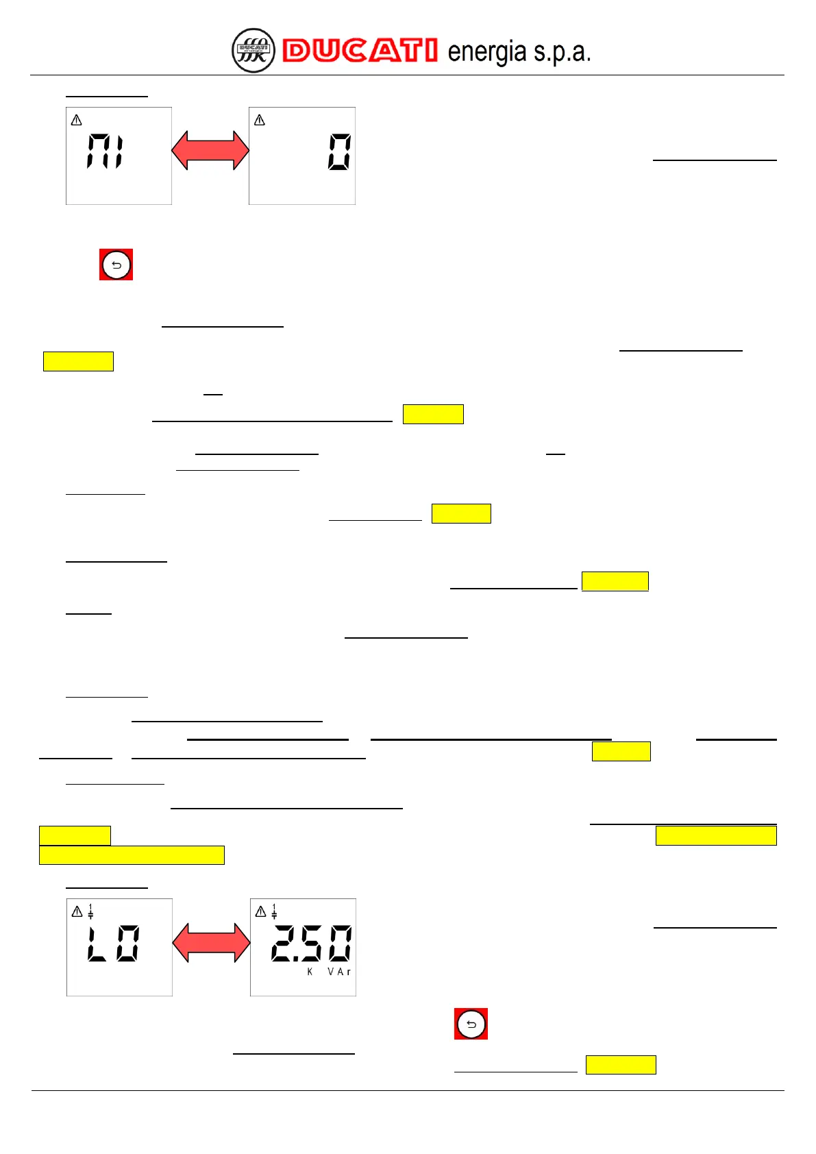
DISPLAYING
Regardless of the current displaying, the alarm will be indicated
with the displaying of the relevant page of the Current alarm menu
that will be alternately shown with the numerical value
corresponding to bank estimated reactive power (in the example,
bank 1 is broken with an estimated power of 2.50kVAr).
The Controller will stay in the above-mentioned screen until key is pressed for more than 2sec (the alarm is
anyway active). Afterwards, the Measurement Menu will be automatically displayed and will show the cosphi value and
the alarm icon on the top left. The alarm will be anyway active in the Current Alarm Menu (Chap. 8.5.1).