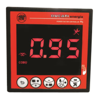
The next displayed page relates to the estimated reactive power ESt of the first capacitor bank. The following screen
will appear:
that will be alternately shown with the numerical value.
NOTE: the displayed value does not relate to the set capacitor nominal voltage, but to the actually measured network
voltage.
The next 4 pages show the estimated reactive power of banks from 2 to 5.
To quit the Statistics Menu and go back to the Measurement Menu press key for more than 2sec.
GO BACK TO USING THE CONTROLLER
GO BACK TO CONTENTS
8.4.2 Alarm statistics
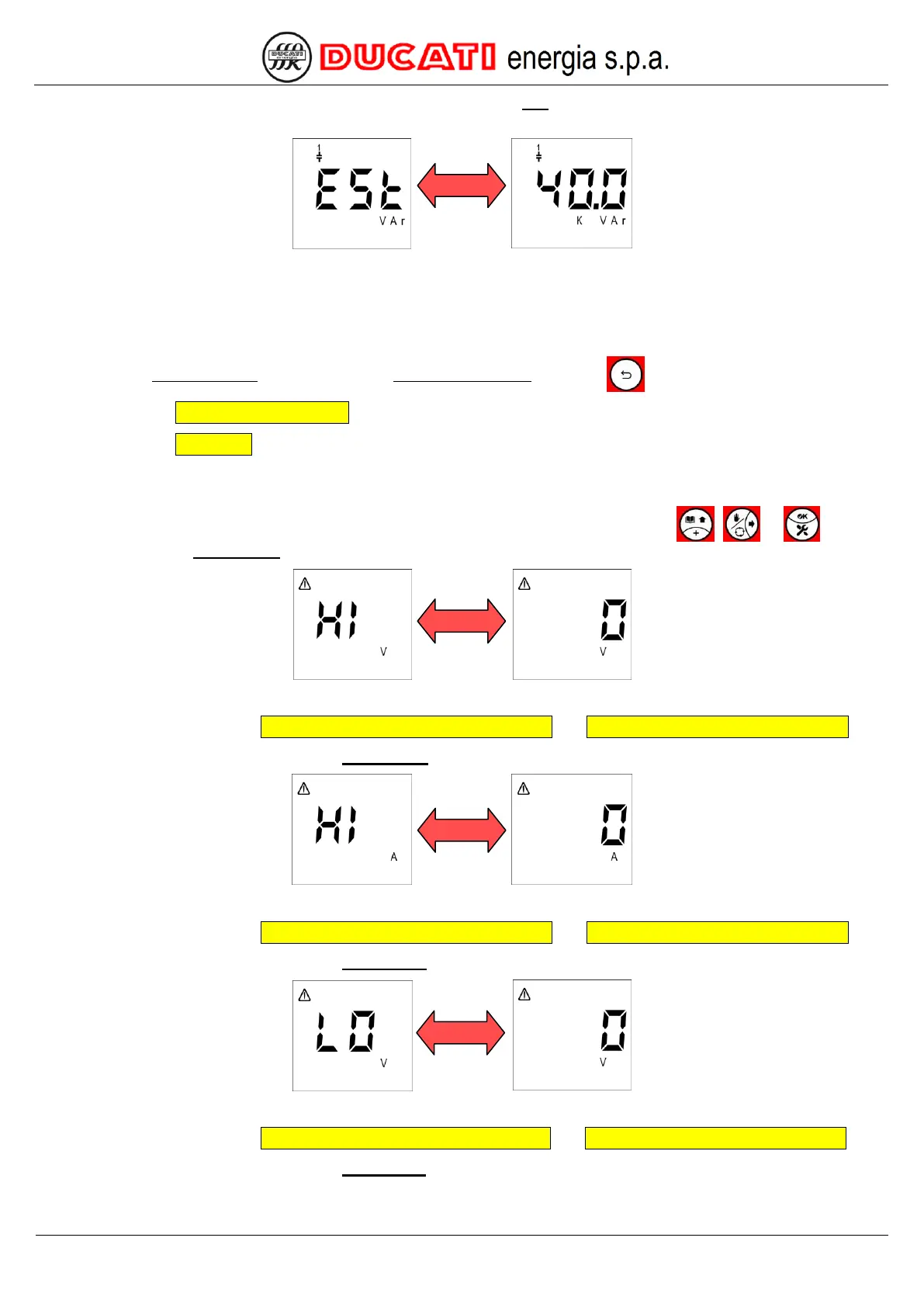
To reach the section devoted to alarm statistics, scroll pages by pressing one of keys , or until the
screen relating to the overvoltage alarm is displayed:
that will be alternately shown with the numerical value corresponding to the alarm activations.
For alarm settings, refer to Chap. 7.5.1 - Overvoltage alarm threshold and Chap. 7.5.2 - Overvoltage alarm delay.
The next displayed page relates to the overcurrent alarm. The following screen will appear:
that will be alternately shown with the numerical value corresponding to the alarm activations.
For alarm settings, refer to Chap. 7.5.3 - Overcurrent alarm threshold and Chap. 7.5.4 - Overcurrent alarm delay.
The next displayed page relates to the low voltage alarm. The following screen will appear:
that will be alternately shown with the numerical value corresponding to the alarm activations.
For alarm settings, refer to Chap. 7.5.5 - Low voltage alarm threshold and Chap. 7.5.6 - Low voltage alarm delay.
The next displayed page relates to the low current alarm. The following screen will appear: