5 CONNECTIONS
For voltage/supply input, current input and relay output connections
GO TO Chap. 5.1 - Basic Connections
For the connections to the serial communication port
GO TO Chap. 5.2 - RS485 serial connection
For the connections of the output relays used as alarm contacts
GO TO Chap. 5.3 - Alarm output connections
GO BACK TO CONTENTS
5.1 Basic Connections
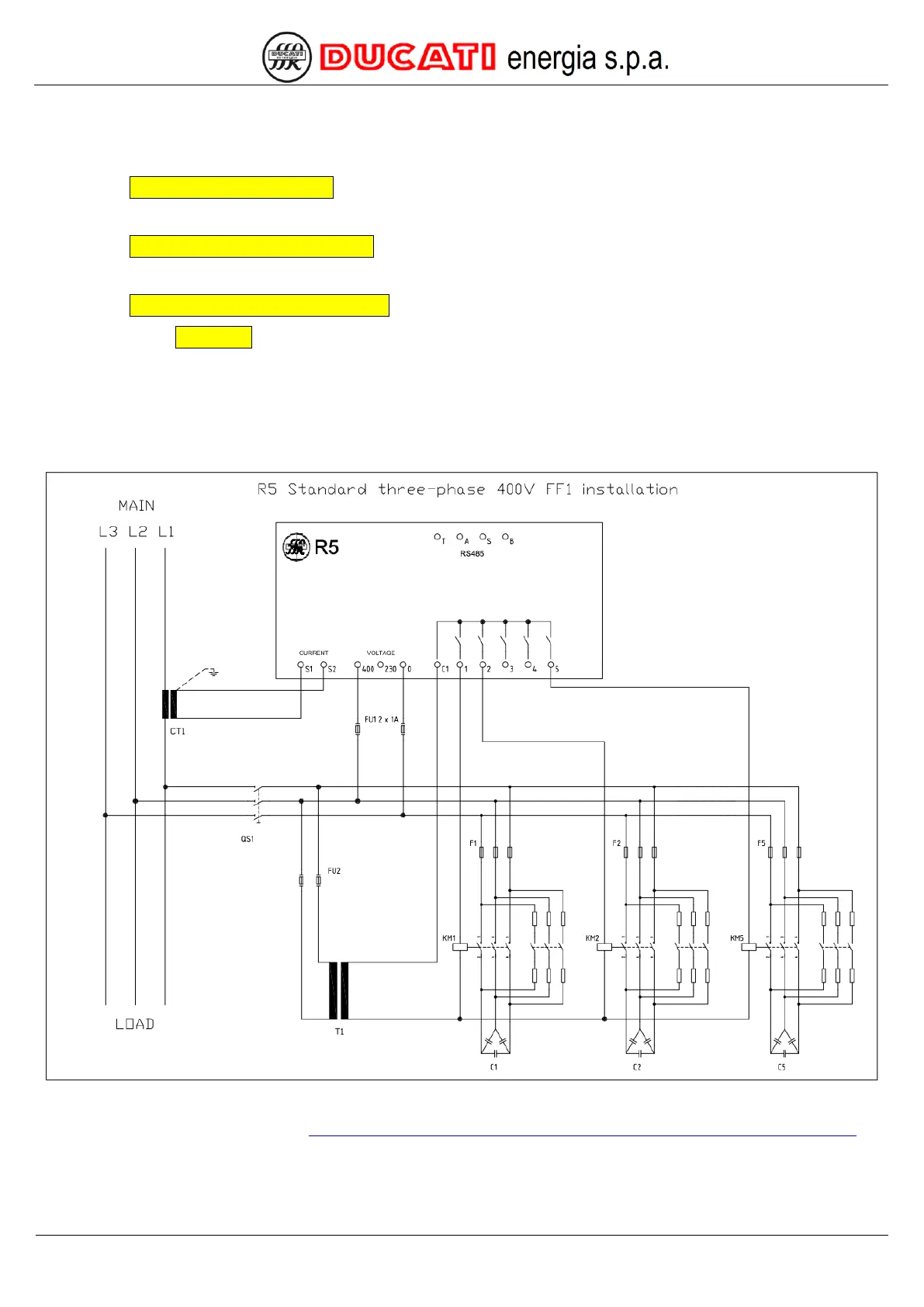
5.1.1 Three-phase network without standard neutral with 400V phase-phase voltage
Connect the R5 controller as indicated in the figure below.
NOTE: the diagram shows a FF1 configuration, for FF2 and FF3 configurations, refer to the complete operating
manual, available at the following link: https://www.ducatienergia.com/product.php?lang=en&id=8&cat=13&product=89
Connect all the available power factor correction banks using terminals from 1 to 5, as indicated for banks 1, 2 and 5.
For the components indicated in the figure (CT1, F1..5, FU2, T1, KM1..5, C1..5 and QS1), refer to the power factor
correction equipment manual and to the manual of the system on which the power factor controller is fitted.