For alarm settings, refer to Chap. 7.5.7 - Low voltage current threshold and Chap. 7.5.8 - Low current alarm delay.
For further information on alarm management, refer to Chap. 8.5.2.4 - Low current alarm.
The next displayed page relates to the THDI alarm that will be
alternately shown with the numerical value corresponding to the
maximum % value measured since alarm activation (10% in the
example shown).
For alarm settings, refer to Chap. 7.5.11 - THDI alarm threshold and Chap. 7.5.12 - THDI alarm delay. For further
information on alarm management, refer to Chap. 8.5.2.5 - THDI alarm.
The next displayed page relates to the THDV alarm that will be
alternately shown with the numerical value corresponding to the
maximum % value measured since alarm activation (10% in the
example shown).
For alarm settings, refer to Chap. 7.5.9 - THDV alarm threshold and Chap. 7.5.10 - THDV alarm delay. For further
information on alarm management, refer to Chap. 8.5.2.6 - THDV alarm.
The next displayed page relates to the temperature alarm that will
be alternately shown with the numerical value corresponding to
the maximum temperature value measured since alarm activation
(65°C in the example shown).
For alarm settings, refer to Chap. 7.5.13 - Temperature alarm threshold and Chap. 7.5.14 - Temperature alarm
delay. For further information on alarm management, refer to Chap. 8.5.2.7 - Temperature alarm.
The next displayed page relates to the power factor
overcorrection alarm that will be alternately shown with the
numerical value corresponding to the most capacitive extreme
value of the target cosphi range defined by parameters Cosphi
setpoint and Cosphi setpoint tolerance (0.99 capacitive in the
example shown).
For alarm settings, refer to Chap. 7.3.1 - Cosphi setpoint, Chap. 7.3.2 - Cosphi setpoint tolerance and to parameter
P.22 – Power factor overcorrection alarm delay (Chap. 7.6). For further information on alarm management, refer to
Chap. 8.5.2.8 - Power factor overcorrection alarm.
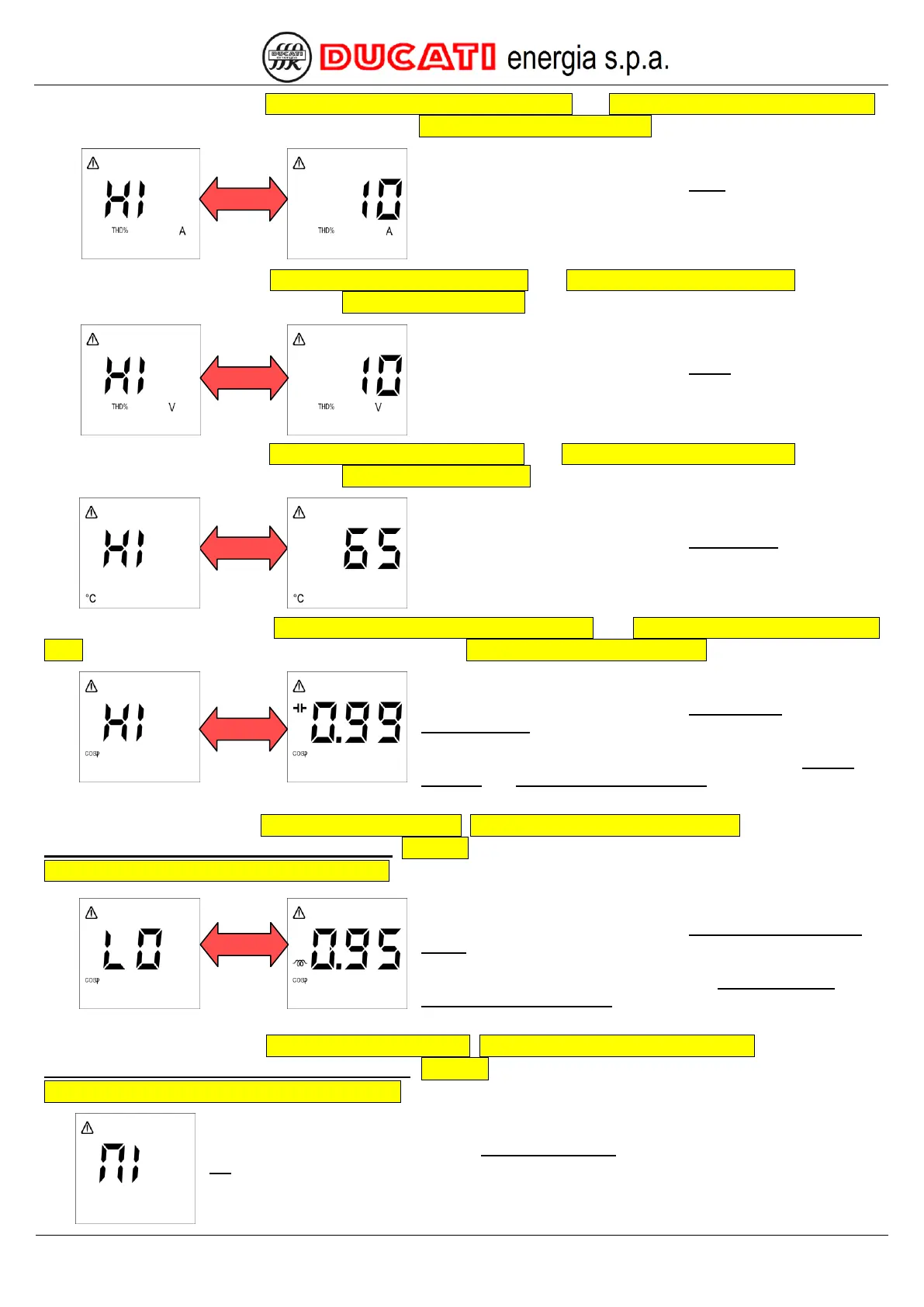
The next displayed page relates to the power factor correction
failed alarm that will be alternately shown with the numerical
value corresponding to the most inductive extreme value of the
target cosphi range defined by parameters Cosphi setpoint and
Cosphi setpoint tolerance (0.95 inductive in the example
shown).
For alarm settings, refer to Chap. 7.3.1 - Cosphi setpoint, Chap. 7.3.2 - Cosphi setpoint tolerance and to parameter
P.23 – Power factor correction failed alarm delay (Chap. 7.6). For further information on alarm management, refer to
Chap. 8.5.2.9 - Power factor correction failed alarm.
The next displayed page relates to the micro-interruption alarm on the network voltage that will
not be alternately shown with any numerical value.