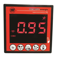
Shift to the screen of the previous parameter / Cancel current change
Change Value of CT Primary (Pri) winding or CT secondary (SEC) winding or Capacitor nominal voltage
(nOM) / Increment value of selected digit
Change Value of CT Primary (Pri) winding or CT secondary (SEC) winding or Capacitor nominal voltage
(nOM) / Decrement value of selected digit
Select next digit during parameter change
Confirm value and pass to the screen of the next parameter
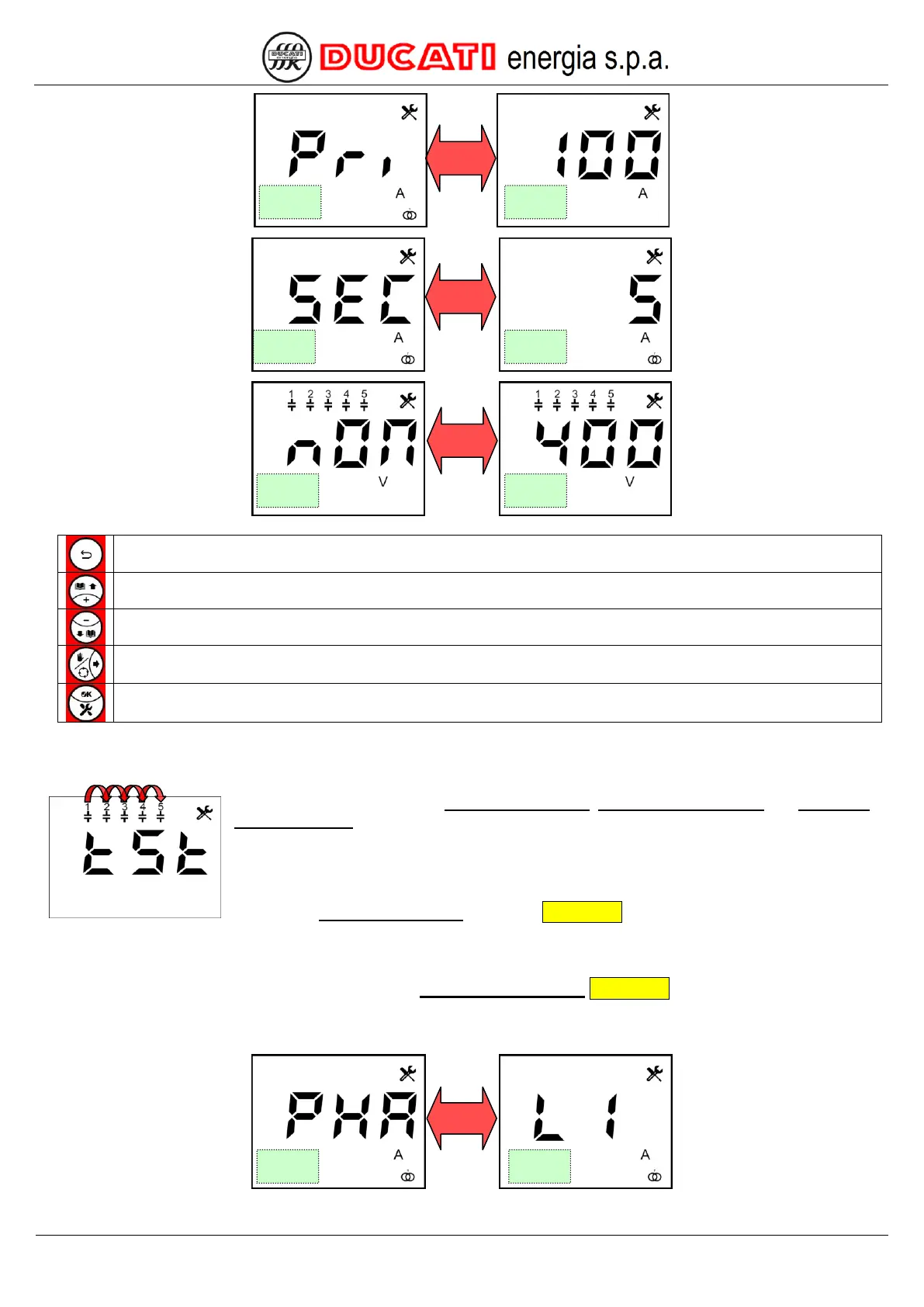
3.)
After setting the values of CT primary winding, CT secondary winding and Capacitor
nominal voltage, the controller will check the voltage/current connections by cyclically
inserting the capacitor banks. After each insertion, the controller will show the calculated
configuration for a few seconds. A minimum of 2 to a maximum of 5 cycles of insertion cycles
are needed, at the end of which the controller will automatically set the type of detected
connection. The duration of a cycle is equal to the greatest value between one minute and the
value of the Re-connection time parameter Chap. 7.2.3.
Should the controller not be able to automatically define the type of configuration due to unfavourable load
conditions, it will show the setting screen of parameter Current reading phase Chap. 7.1.3 that will have to be manually
entered (or confirmed).