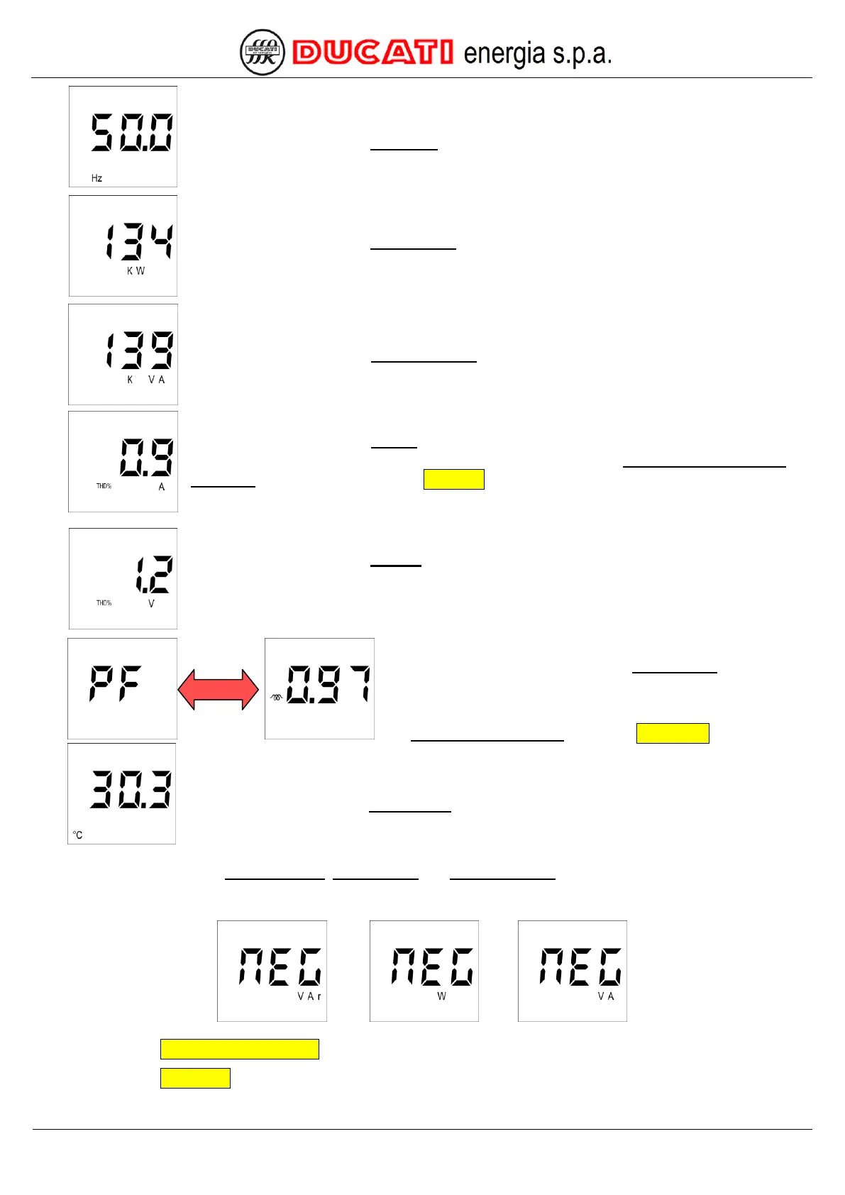
The next page relates to the frequency, which is recognisable by the measurement unit in [Hz].
The next page relates to the active power, which is recognisable by the measurement unit in [W].
The next page relates to the apparent power, which is recognisable by the measurement unit in
[VA].
The next page relates to the THDI%, which is recognisable by the labels “THD%” and “A”. If the
measured harmonic current is below the value defined by parameter P.24 – THDI invalidation
threshold (for further details refer to Chap. 7.6) the display will show “---“.
The next page relates to the THDV%, which is recognisable by the labels “THD%” and “V”.
The next displayed page relates to the power factor, where “PF”
will be alternately shown with the numerical value with the
indication of the type of load (inductive or capacitive). Should
measurement not be available (due to a current 0.7% lower than
the CT Secondary winding parameter Chap. 7.1.2) the controller
will show “---“.
The next page relates to the temperature inside controller, which is recognisable by the
measurement unit in [°C].
NOTE: For the values of reactive power, active power and apparent power, if the measured value is equal to
one MVAr, one MW and one MVA respectively, the following screen will be respectively displayed alternately with the
numerical value.
GO BACK TO USING THE CONTROLLER
GO BACK TO CONTENTS