o after a time (in sec) equal to parameter Low current alarm delay Chap. 7.5.8, if the current reading of the
R5 Controller goes below the value defined by parameter Low voltage alarm threshold.
NOTE: if the measured current is equal to or lower than 0.7% of the CT primary winding, only the immediate
activation will take place.
MANAGEMENT
If the activation of the low current alarm is triggered by a current value below the minimum measurable value (0.7%
CT primary winding) there will be a "slow" disconnection of all banks, one at a time, and with a delay between them
equal to P.4 – Transient time during disconnection (Chap. 7.6). This process takes place in automatic power factor
correction mode for all the inserted banks whose Step n function (n=1,2,3,4,5) Chap. 7.2.5 has been set to “CAP” or
“ON” and in manual power factor correction mode (refer to Chap. 8.8 - Manual power factor correction mode) for all the
banks whose status has been set to "ON".
If the activation of the low current alarm is triggered by a higher current value (set through parameter Low current
alarm threshold) the inserted banks will not be affected in any way.
At the same time, the relay outputs set as "ALA" and associated to the "THLA" or "ALL" alarm will be activated unless
parameter P.25 – Alarm masking management (Chap. 7.6) has been set to mask the alarms under defined operating
conditions
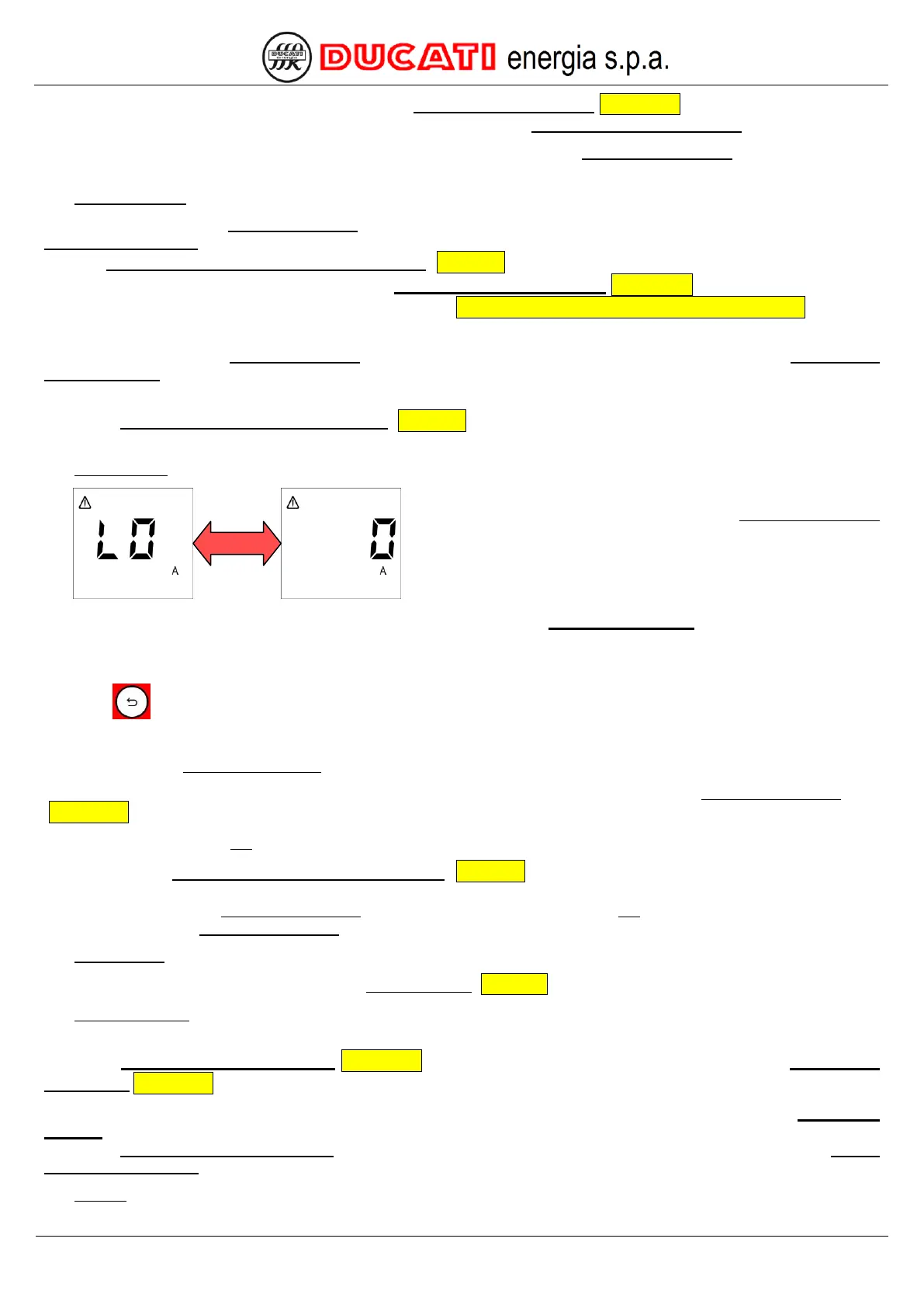
DISPLAYING
Regardless of the current displaying, the alarm will be indicated
with the displaying of the relevant page of the Current alarm menu
that will be alternately shown with the numerical value
corresponding to the minimum current value measured since alarm
activation (0A in the example shown).
NOTE: if the measured current is equal to or lower than 0.7% of the CT primary winding, only the immediate signal
will take place.
The Controller will stay in the above-mentioned screen until:
- key is pressed for more than 2sec (the alarm is anyway active);
- alarm is deactivated or manually reset by the operator.
Afterwards, the Measurement Menu will be automatically displayed and will show, respectively:
- the cosphi value and the alarm icon on the top left. The alarm will be anyway active in the Current Alarm Menu
(Chap. 8.5.1);
- the cosphi value, but not the alarm icon.
If, parameter P.25 – Alarm masking management (Chap. 7.6) has been set to mask the alarms under defined
operating conditions, the previous screen will be temporarily displayed for 3sec. The alarm will then automatically go back
to the first screen of the Measurement Menu by displaying the cosphi value, but not the alarm icon. The alarm will be
anyway present in the Current Alarm Menu.
STATISTICS
The alarm counter will be increased in the Statistics Menu (Chap. 8.4) at every occurrence.
DEACTIVATION
The alarm is automatically deactivated if the current reading of the R5 Controller stays above the value defined by
parameter Low current alarm threshold Chap. 7.5.7 for a time (in sec) equal to the value of parameter Low current
alarm delay Chap. 7.5.8.
NOTE: if the activation has been caused by a measured current value equal to or lower than 0.7% of the CT primary
winding, as soon as the current value goes above this threshold (and not necessarily above the value defined by
parameter Low current alarm threshold), the controller will start inserting capacitor banks again based on the Step n
function (n=1,2,3,4,5) they are associated to and on the automatic or manual power factor correction mode.
RESET