15 | Examples of settings
D-ISC 100 x xx2
181
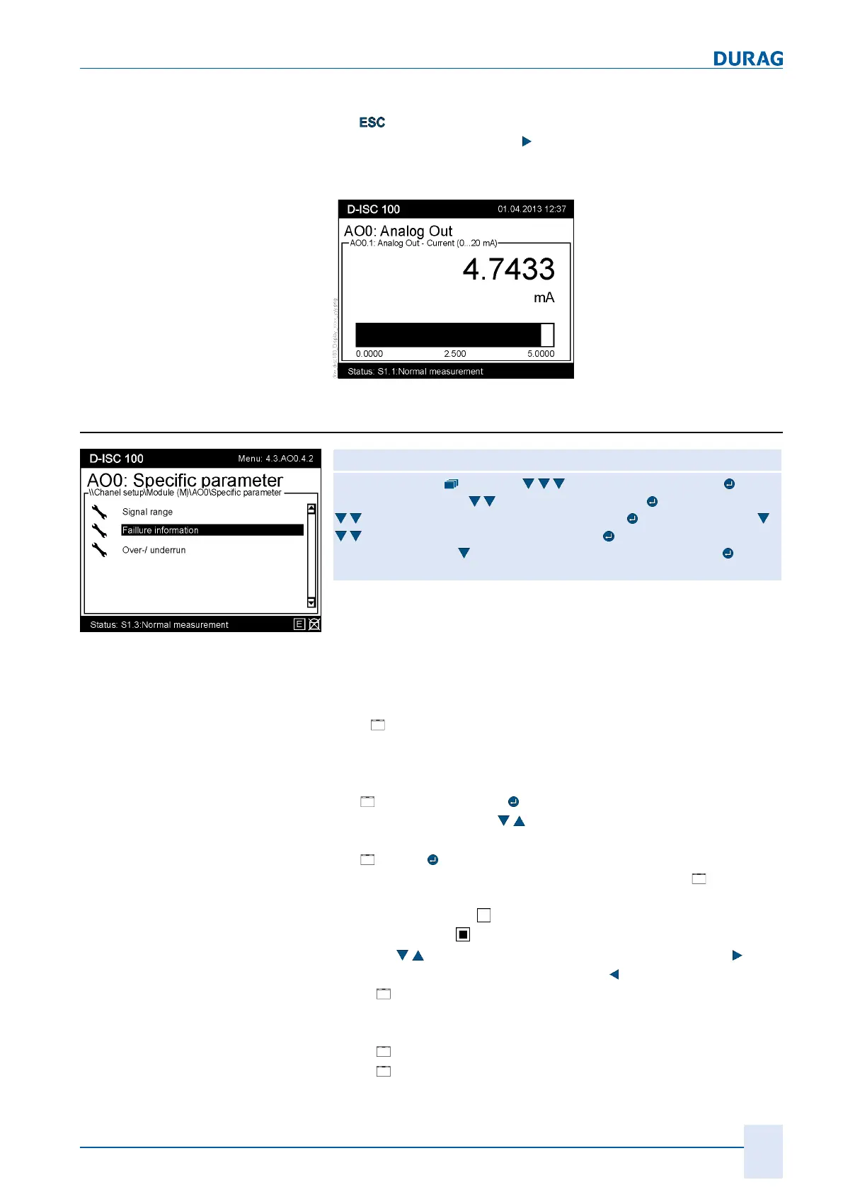
View display of the analogue
outputs
If you wish to check the display of the analogue outputs, press
the
key multiple times to return to the standard display. Once
there, press the arrow key (
) (several times if necessary) to se-
lect the display for the analogue output (AO0). The relevant dis-
play then looks like this:
Fig.15.40: Display analogue OUT (example)
15.10.2 Example: Setting the error information
Fig.15.41: Analogue output
specific parameter
D‑ISC100 menu path:
Standard display (menu1) Channelsetup (menu4) Chan-
nelsetup (menu4.1)
Module(M) (menu 4.3) (menu4.3.1) e.g.
Analogue output internal (menu4.3.AO0) (menu4.3.AO0.1)
Specific parameter (menu 4.3.AO0.4) Signalrange
(menu4.3.AO0.4.1
Failure information (menu4.3.AO0.4.2)
=Failure value [mA] MENU 4.3.AO0.4.2.1
The signal range of the analogue output is from 0 … 23mA. The
range from 4 … 20mA is reserved for measured values. The
range from 0 … 4mA and the range from 20 … 23mA can also
be activated by the analogue output. These ranges can be used
to forward information about faults.
The "
Failure information" menu item (menu 4.3.AOx.x.x) can
be used to make the first selection as to whether this fault report-
ing function is to be used, and which events should trigger the
sending of a fault report.
● [
Failure value [mA]
Use the arrow keys ( ) to specify the value that should be
output in such an event (see setup) (default: 2mA)
● [
Setup]
Mark the event(s) for which the value set as the [ Failure
value] is to be output.
An empty square
means "not active (not selected)";
a solid square
means "active (selected)". Use the arrow
keys (
) to select the option(s). The right arrow key ( ) ac-
tivates the option, the left arrow key (
) deactivates it.
○
[
Indicate fault status on analogue output, if:]
If this setting is deactivated, all the following error mes-
sages are suppressed (deactivated).
○
[
Analogue output module faulty (common fault)]
○
[
Source module faulty (e.g. sensor)]
 Loading...