15 | Examples of settings
182
D-ISC 100 x xx2
○
[
Source module off-line (e.g. sensor)]
Signal source (e.g. sensor) not connected
○
[
Source module not assigned (e.g. sensor)]
Signal source (e.g. sensor) not assigned
○
[
Source module not available (e.g. sensor)]
Signal source (e.g. sensor) not available
○
[
Device (D-ISC100) faulty]
Fault in the Universal control unit
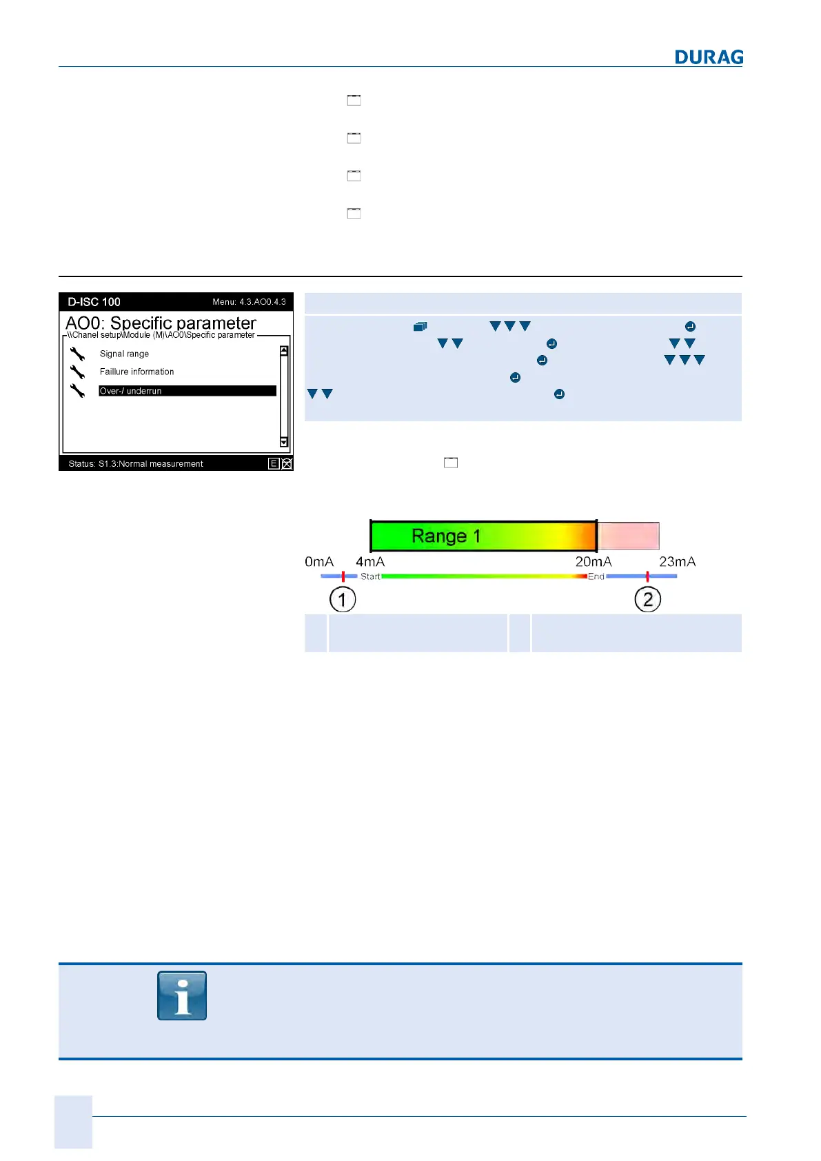
15.10.3 Example: Setting the overruns / underruns
Fig.15.42: Analogue output
specific parameter
D‑ISC100 menu path:
Standard display (menu1) Channelsetup (menu4) Chan-
nelsetup (menu4.1)
Modules (M) (menu4.3.1) e.g. Ana-
logue output internal (menu4.3.AO0)
(menu4.3.AO0.1) Spe-
cific parameter (menu4.3.AO0.4)
Signal range (menu4.3.AO0.4.1)
Over-/underrun (menu4.3.AO0.4.3)
=MENU 4.3.AO0.4.3.1
The settings for the [
over-/underrun] can be used to specify
what actions should be taken in the event that limit values are
overrun/underrun.
1
Underrun 0 … 4mA (typic-
ally 2mA)
2
Overrun 20 … 23mA (typically
22mA)
Fig.15.43: Signal overrun / underrun
The signal range of the analogue output is from 0 … 23mA. The
range from 4 … 20mA is reserved for measured values. The
range from 0 … 4mA and the range from 20 … 23mA can also
be activated by the analogue output. These ranges are also nor-
mally used for signal outputs. Even if the signal range was previ-
ously set to 4 … 20mA, the signal can take values outside this
range and be used. In some cases, it may even be desirable that
the measured value signal is
not
directly capped at the specified
limits.
The underrun value is typically 2mA, while the overrun value is
22mA. Only when these limits are undershot or overshot will
(optionally) the corresponding overrun / underrun values be out-
put.
Comply with the settings for the overruns / underruns in the local
instructions!
Not all official measurement locations in all regions of the EU
permit the use of "Underrun".
 Loading...