15 | Examples of settings
D-ISC 100 x xx2
183
After [
over-/underrun] has been called up, the following options
are available for selection:
● [
Overrun value [mA]]
The overrun output value is adjustable; the overrun default
value is 22 [mA].
The value can be adjusted using the arrow keys (
) or the
on-screen keyboard [}204] (see also [}70]).
● [
Underrun value [mA]]
The underrun output value is adjustable; the underrun default
value is 2 [mA].
The value can be adjusted using the arrow keys (
) or the
on-screen keyboard (see also [}70]).
● [
Setup]
Additional settings for over-/underrun can be adjusted under
this menu item.
An empty square
means "not active (not selected)";
a solid square
means "active (selected)". Use the arrow
keys (
) to select the option. The right arrow key ( ) activ-
ates the option, the left arrow key (
) deactivates it.
○
[
Overrun value active]
If this option is active, the previously set [
overrun value
[mA]] will be evaluated as follows.
○
[
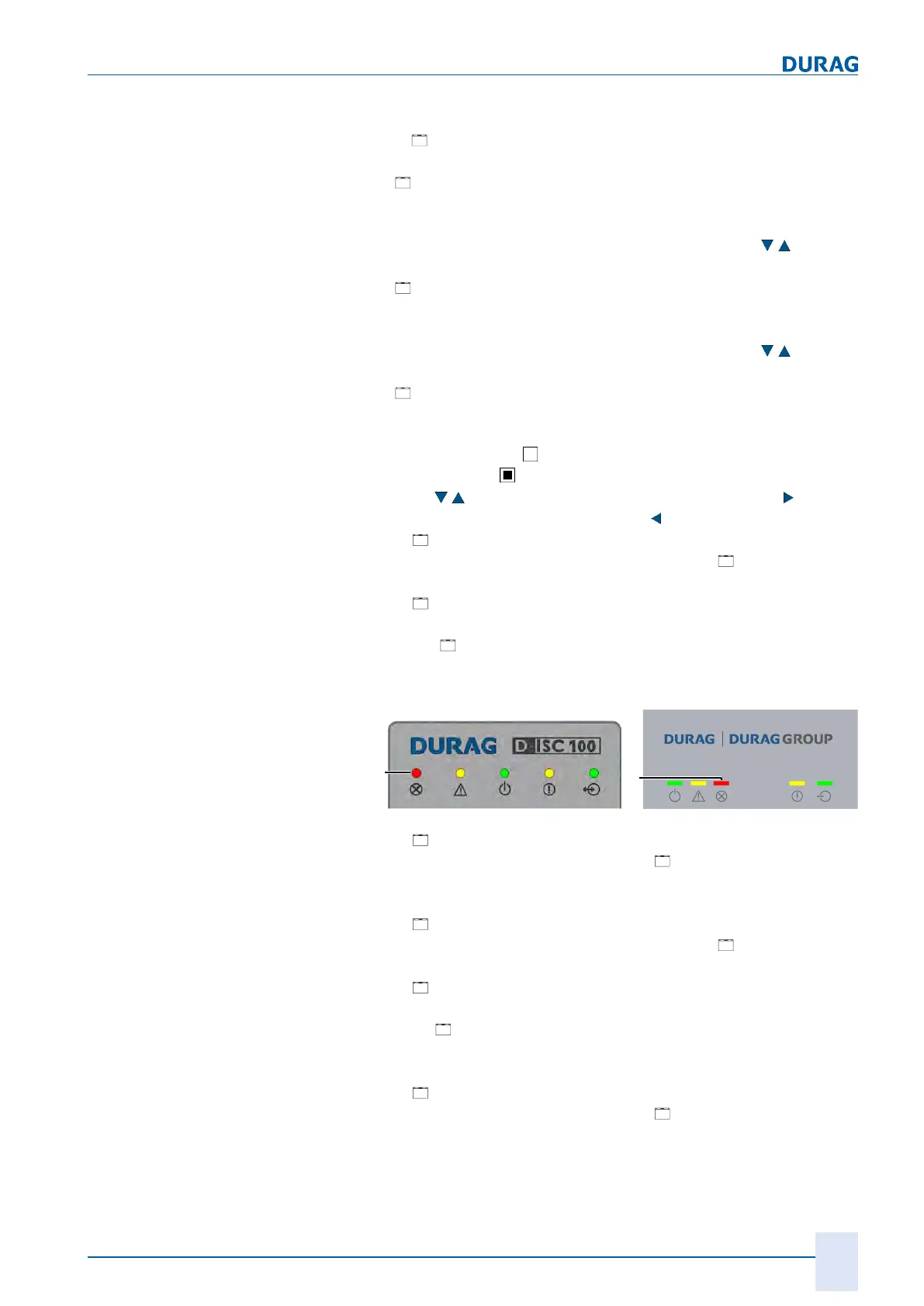
Overrun set fault (F)
If this option is active, the fault status is applied when the
set [
Overrun value [mA]] is exceeded and the red LEDs
on the module and on the D‑ISC100 (see illustration below
(F)) are activated.
Fig.15.44: Fault status (F) display via red LEDs
○
[
Overrun hold value]
If this option is active, when the [
Overrun value [mA]] is
reached, this value will be held until the measured signal
falls back below this value again.
○
[
Underrun value active]
If this option is active, the previously set [
Underrun value
[mA]] will be evaluated as follows.
○
[
Underrun set fault (F)
If this option is active, the fault status is applied when the
set
Underrun value [mA] is undershot and the red LEDs
on the module and on the D‑ISC100 (see illustration below
(F)) are activated.
○
[
Underrun hold value]
If this option is active, when the [
Underrun value [mA]] is
reached, this value will be held until the measured signal
rises back above this value again.
 Loading...