4 | Installation and commissioning
30
D-ISC 100 x xx2
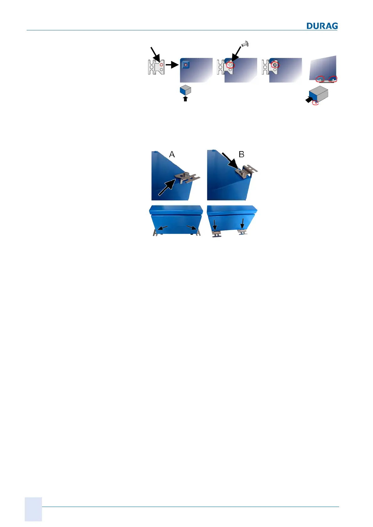
The clips should not project laterally beyond the outline of the
casing. Therefore, for the fastenings use the hole in the clip
next to the outer edge. The figure below shows attachment to
the long edge (
A
) and the short edge (
B
).
Maximum torque when tightening the screws: 10Nm.
2.
Install the Universal control unit onto the wall clips on the wall.
The
installation drawing
can be found in Section 14 Dimen-
sioned drawings [}151].
Installation of the D-ISC 100 P (purge air supply)
● When choosing the installation location and during the install-
ation of the D‑ISC100 P, the parameters specified in the
technical data must be complied with.
● The intake air must be as dry as possible (< 95% relative hu-
midity), and free from dust and oil.
● The D‑ISC100 P is installed with the cable glands facing
downwards. Unused openings must be sealed to prevent the
ingress of moisture.
● The D‑ISC100 P must be freely accessible for air filter
changes.
Laying the purge air hoses
● The purge air hose is designed for a default ambient temper-
ature of approx. −25 … +80°C. Alternative hoses are avail-
able.
● Do not select too narrow a bend radius in comparison to the
hose diameter (risk of kinking, leading to: purge air failure).
● The hoses are not resistant to tension. Do not hang the hoses
in free loops under their own weight. Fit supports at reason-
able intervals.
● Do not use force, e.g. to drag the hose through excessively
narrow openings in walls.
 Loading...