4 | Installation and commissioning
D-ISC 100 x xx2
49
Replacing an existing module
(with the same module type)
o An existing module is to be replaced with another module of
the same type.
1.
The old module is
not
removed from the D‑ISC100 configura-
tion using the D‑ISC100 user interface.
2.
Disconnect the D‑ISC100 from the power. Then disassemble
the module from the top hat rail.
3.
Assemble the new module in the location of the old module
on the top hat rail. The remaining modules are not moved.
4.
Switch the power to the D‑ISC100 back on.
5.
Correct the parameterisation of the new module using the
D‑ISC100 user interface. See also Section 10.4.3 Modules
(M) (expansion module, hardware) [}126].
Replacing an existing module
(with a different module type)
o An existing module is to be replaced with a module of a differ-
ent type.
1.
To this end, the module being replace is removed (as de-
scribed under "Remove module").
2.
The new module is then added to the system (as described
under "Installing a new module).
Assembly:
The following assembly is explained using the example of the
D‑ISC100 M.
Fig.4.12: Undo the terminal end holders.
You can find the parts designation on page [}24].
Proceed as follows:
o The D‑ISC100 is de-activated.
o The housing of the D‑ISC100 is opened.
1.
Undo the terminal end holder on the right-hand side of the
CPU module (or the most recently assembled module). Use a
screwdriver to do so. Lever the terminal end holder out of the
top hat rail as shown in the figure on the left.
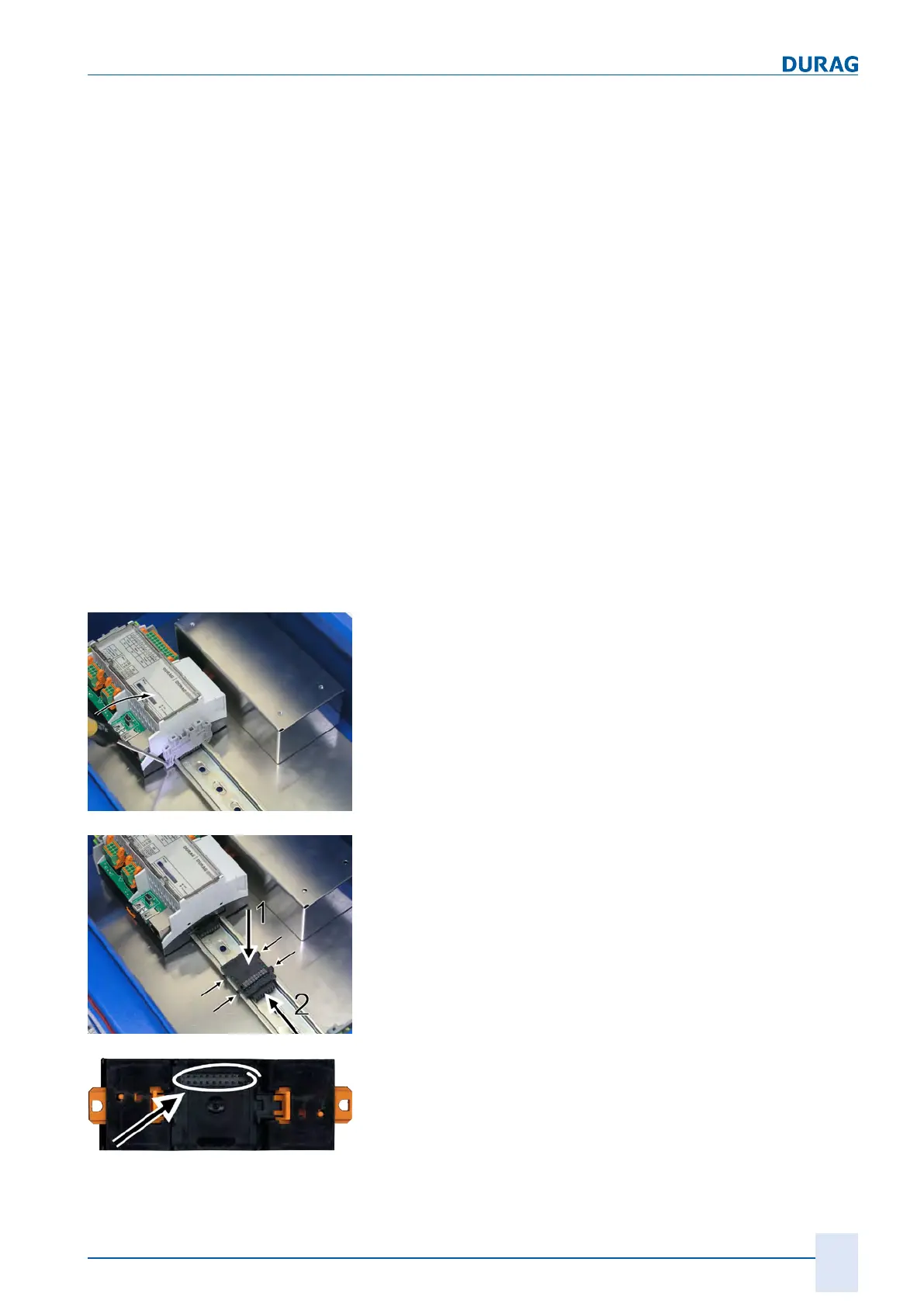
Fig.4.13: Engaging the bus connector
2.
Engage a bus connector onto the top hat rail (figure on the
left - 1). The plug connection at the top is on the right-hand
side.
3.
Slide the bus connector that has been engaged on the top hat
rail along the rail towards the left (figure on the left - 2) until it
is connected to the existing plug connection underneath the
CPU module (or the most recently installed module).
4.
Hold the top hat rail module immediately to the right of the
CPU module (or the most recently installed module) above
the top hat rail. The module's plug connection (figure on the
left) must be aligned above the top plug connection of the bus
connector.

 Loading...