4 | Installation and commissioning
50
D-ISC 100 x xx2
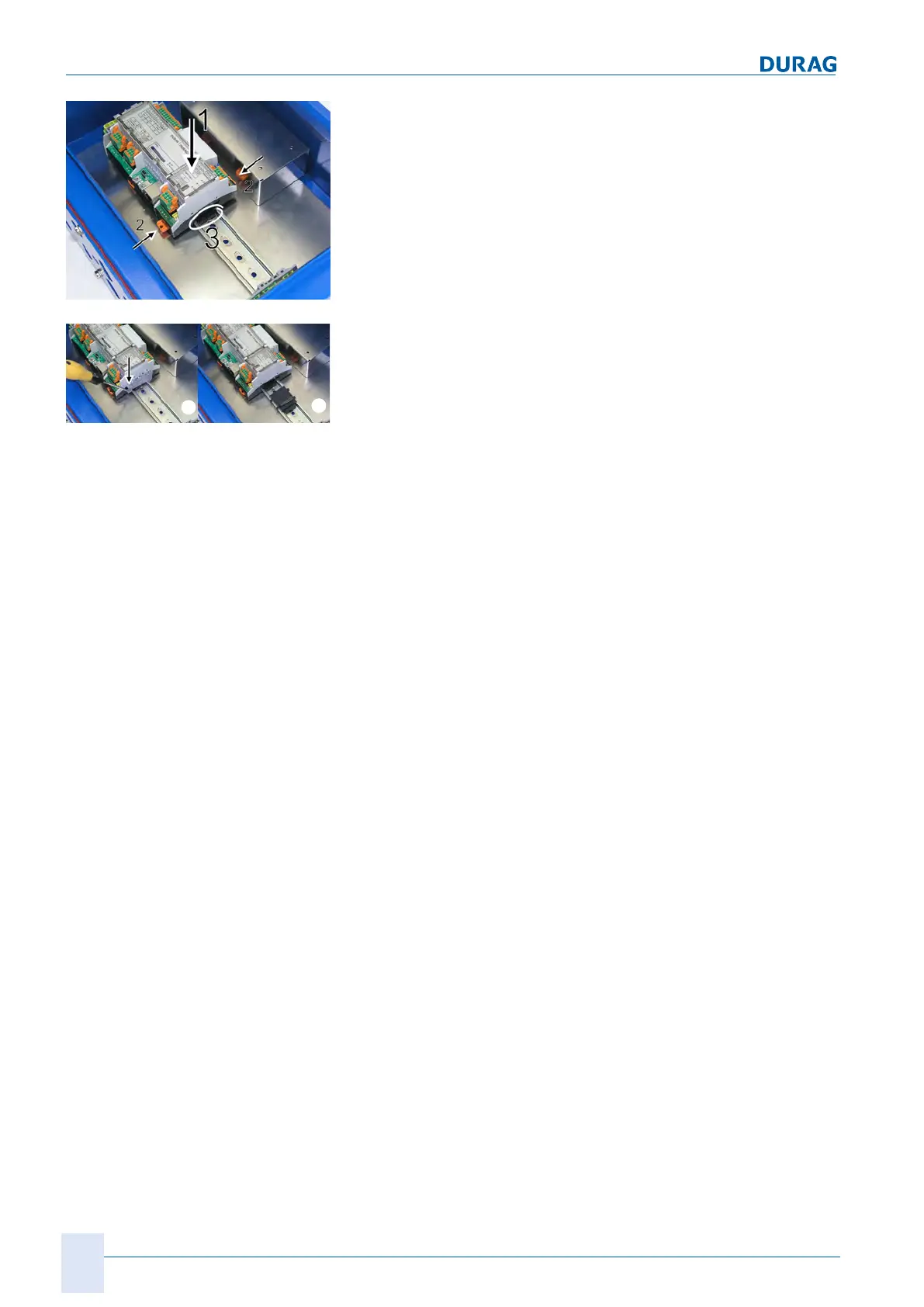
Fig.4.14: Attaching the top hat rail module
5.
Now carefully push the top hat rail module onto the top hat
rail (figure on the left - 1).
6.
Lock the top hat rail module onto the rail by pushing both tabs
(figure on the left - 2) towards the top hat rail.
✓ The plug connection for the bus connector is visible under-
neath the installed top hat rail module (figure on the left -
3). The next module can be connected here.
Fig.4.15: Completing installation
7.
Installation is completed by attaching the terminal end holder
(figure on the left - a).
Position the terminal end holder as closely as possible
against the right-hand side of the installed module. Mount the
terminal end holder here, with the upper part inside the top
hat rail.
8.
Push the bottom part downwards using a screwdriver placed
into the notch above the retaining lug. At the same time, push
it towards the centre of the top hat rail until the terminal end
holder engages in the top hat rail.
o If multiple modules are to be installed, leave out the final ter-
minal end holder to start with. Repeat the installation steps for
each additional module as described from step2.
1.
Then switch on the power to the D‑ISC100.
2.
After installation, the new module will be found by the
D‑ISC100 user interface and will be automatically added to
the system (see Section 10.4.3 Modules (M) (expansion mod-
ule, hardware) [}126] et. seq.).
✔ Configure* the module using the D‑ISC100 user interface,
i.e. enter the required parameters for the new module. Install-
ation is then complete. The device can now be used.
_______________
*see also
15.10 Examples: Assignment of the analogue output (current
output) [}173] ff.
15.11 Example: Assignment of digital outputs [}184] ff.
15.12 Example: Assignment of digital inputs [}187] et. seq.

 Loading...