15 | Examples of settings
D-ISC 100 x xx2
187
In both cases, the filled square means that there is current flow-
ing through the relay
coil
. In conjunction with the switches for the
NO/NC relay switching (see (45) e.g. in Section 3.3.7 Expansion
modules [}24]), this may result in a closed or opened relay.
15.12 Example: Assignment of digital inputs
The D‑ISC100 can be fitted with additional digital IN modules.
Each module extends the system by 8 digital inputs.
The digital inputs are needed in order for external signals, such
as from a central PLC [}204], to prompt the system to perform
various specifiable actions. Such actions (depending on the
sensor to be activated) might for instance be to switch the sensor
to maintenance mode, to start a control cycle or to perform a
zero point check.
For the individual steps, proceed in accordance with the
D‑ISC100 menu path (for an explanation of this, see Section7.1
Navigation guide within this manual [}79]). Comments on the
settings are included in the appropriate text where necessary.
D‑ISC100 menu path:
Standard display User mode (menu1) Channel setup
(menu4)
D−ISC100 (D) (menu4.1) Modules (M) (menu4.3)
(e.g. on:) DI
x
Digital input (menu 4.3.DIx.1) DIx: Digital in-
put (menu4.3.DIx.1)
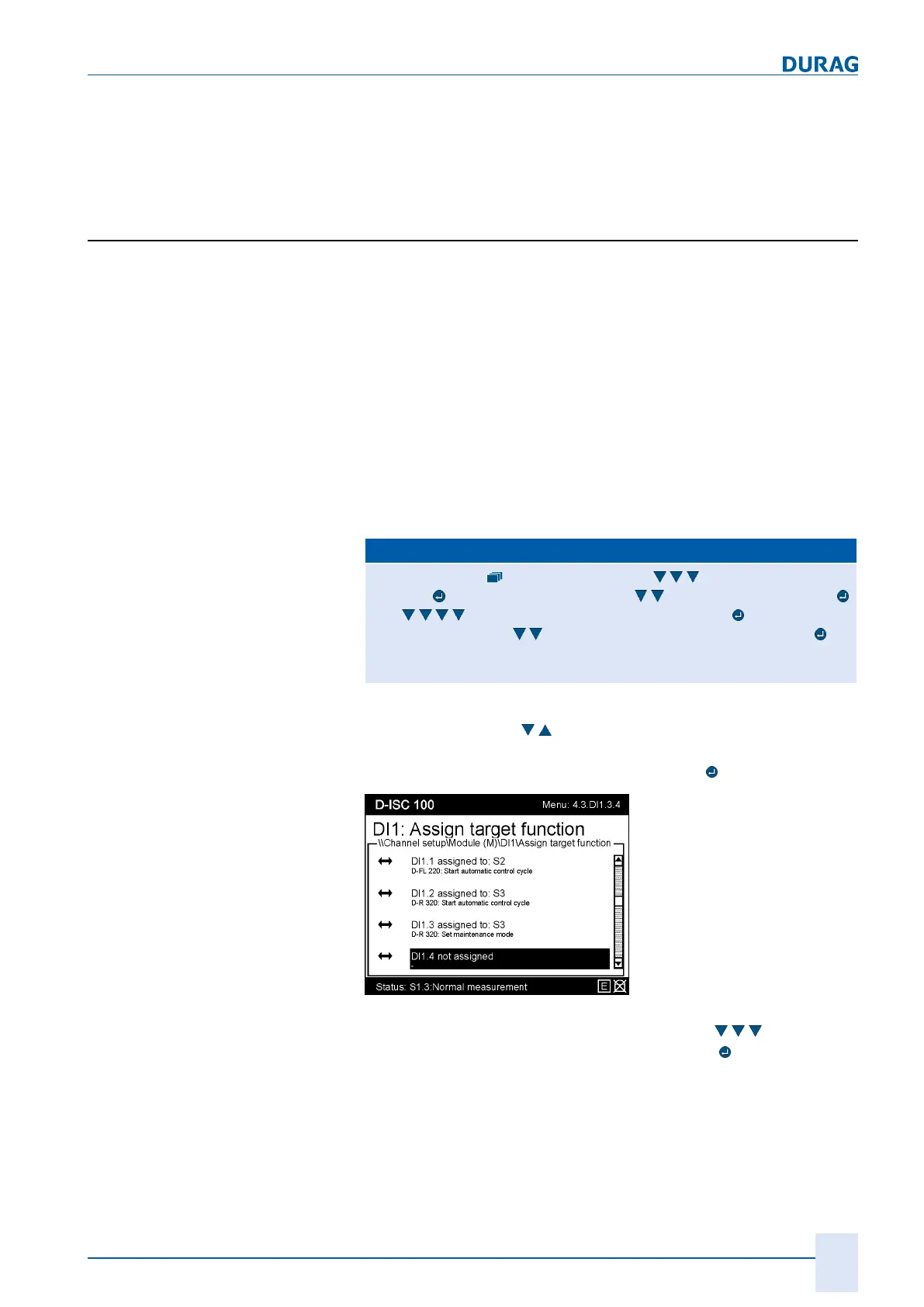
Assign target function (menu4.3.DIx.3)
= MENU 4.3.DIx.3.1
(x stands for the number of a module)
Use the arrow keys (
) to firstly select one of the 8 digital in-
puts to which you want to assign an action (in this example
DI1.4). Confirm the selection by pressing the
key.
Fig.15.53: Action list of the digital inputs
Then assign the required sensor: in this case (
) "S2 D-
FL220". Confirm the selection by pressing the
key.

 Loading...