15 | Examples of settings
186
D-ISC 100 x xx2
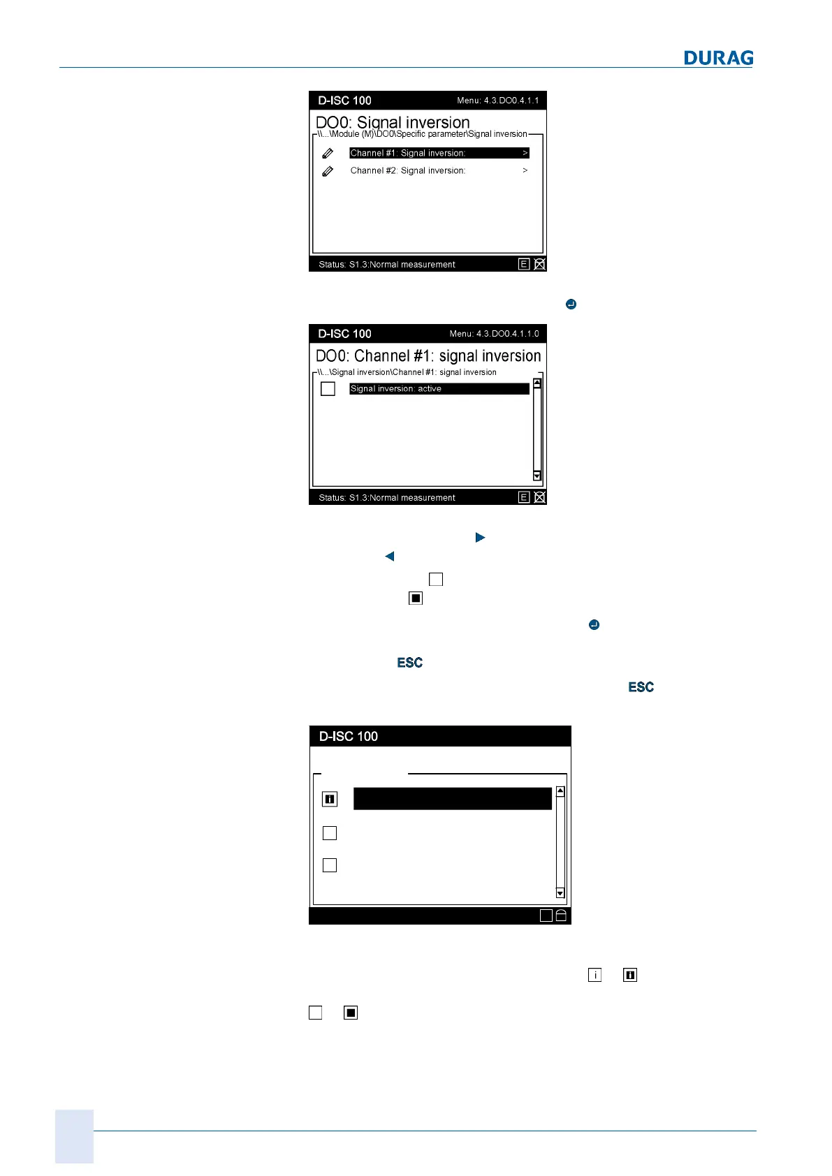
Fig.15.50: Inverting the signal
Confirm the selection by pressing the
key.
Fig.15.51: Activating signal inversion
Use the right arrow key (
) to activate the inversion; use the left
arrow key (
) to deactivate it.
An empty square
means "not active (not selected)";
a solid square
means "active (selected)".
If you exit the menu item by pressing the
key, the setting will
be loaded and saved in the system. If you exit the menu item by
pressing the
key, the setting will not be loaded.
If necessary, check the setting by pressing the
key multiple
times to return to the display of the digital output:
DO0: Digital output
Status: S1.3:Normal measurement
15.03.2017 11:55
DO0.1 assigned to D
Fault (F)
DO0.2 assigned to S1
Fault (F)
DO0.3 not assigned
-
DO0: Digital output
E
Fig.15.52: Display digital output
In the illustration above, the first channel is linked to the inverted
output of an error message, indicated by
or . The second
channel is linked to a non-inverted error message, indicated by
or .

 Loading...