15 | Examples of settings
D-ISC 100 x xx2
185
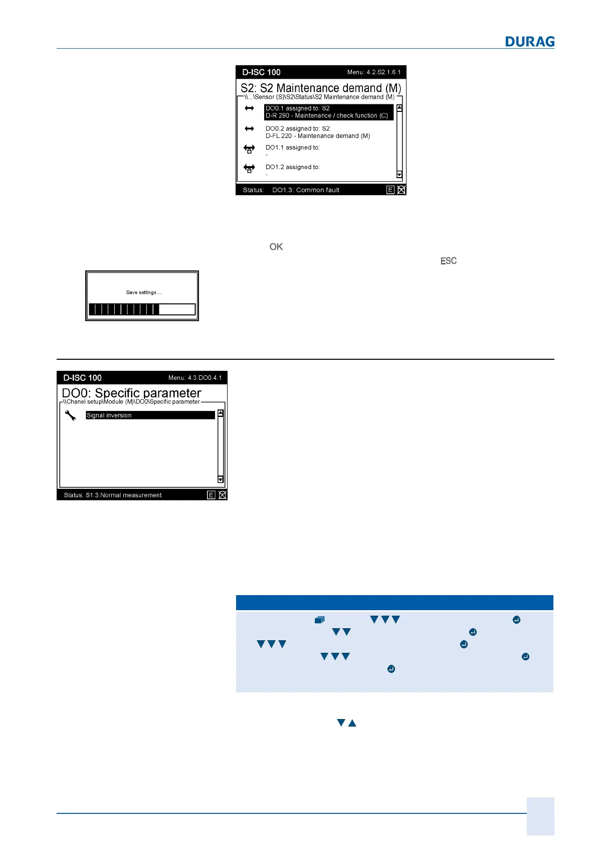
Fig.15.47: Menu 4.2.S2.1.6.1
While editing parameters:
● The entry is temporarily loaded into the device by pressing
the
key.
● The entry is discarded by pressing the
key.
Fig.15.48: Message when saving
The change will be loaded from the temporary to the permanent
device memory on return to the measured value/status display.
15.11.1 Example: Signal inversion setup (digital outputs)
Fig.15.49: Digital output
specific parameter
The status reports assigned to the digital outputs can also be
output as inverted
signals
.
Let us assume that a digital output has been assigned as a
status report for a fault situation. For instance, a red lamp should
light up in the control room in the event of a fault. The lamp is not
illuminated if no fault is present.
A power failure on the D‑ISC100 should also be considered a
fault. In this case however one supposes that this fault would
pass unnoticed.
Let us therefore invert the signal for the fault situation. In this
case a green lamp is actuated. Now if there is a fault in the sys-
tem the green lamp goes out. But the green lamp also goes out
in the event of a power failure. This error indication can thus lead
to a response in either fault situation.
Proceed as follows if you wish to invert the signal:
D‑ISC100 menu path:
Standard display (menu1) Channelsetup (menu4) Chan-
nelsetup (menu4.1)
Channel setup (menu4.3) (menu4.3.1)
e.g.
Digital output internal (menu4.3.DO0) Status
(menu4.3.DO0.1)
Specific parameter (menu4.3.DO0.4) Sig-
nal inversion (menu4.3.DO0.4.1)
=(MENU4.3.DO0.4.1.1)
Use the arrow keys (
) to select the channel/channels to be in-
verted.
 Loading...