8 | Display setup menu 2
86
D-ISC 100 x xx2
A restart and the resulting application of the "Measurement dis-
play after system start" therefore sets the "Current measurement
display" back to the default setting.
The "Current measurement display" can be stored as the "Meas-
urement display after system start".
Scrolling through the
measurement displays
drw_disc100_Display_0001_S2.png
1
2
34
5
01.04.2013 12:37
Status: S1.1: Normal measurement
10.02
mA
0.00 10.00 20.00
01.04.2013 12:38
Status: S1.1: Normal measurement
D:D-ISC 100
Status of all channels
Normal measurement
Normal measurement
No messages
01.04.2013 12:37
Status: S1.1: Normal measurement
747.5
SL
0.0 1000.0 2000.0
01.04.2013 12:38
Status: S1.1: Maintenance / check function (C)
DO0: Digital Out
DO0: Digital Out
DO0.3 assigned to: S1.1
Maintenance demand (M)
DO0.2 assigned to: S1.1
Maintenance / check function (C)
DO0.1 assigned to: S1.1
Fault (F)
01.04.2013 12:38
Status: S1.1: Normal measurement
DI0: Digital In
DI0: Digital In
DI0.1 not assigned
-
D:
S1.1:
S1.2:
S1.3:
S1.4:
Normal measurement
Normal measurement
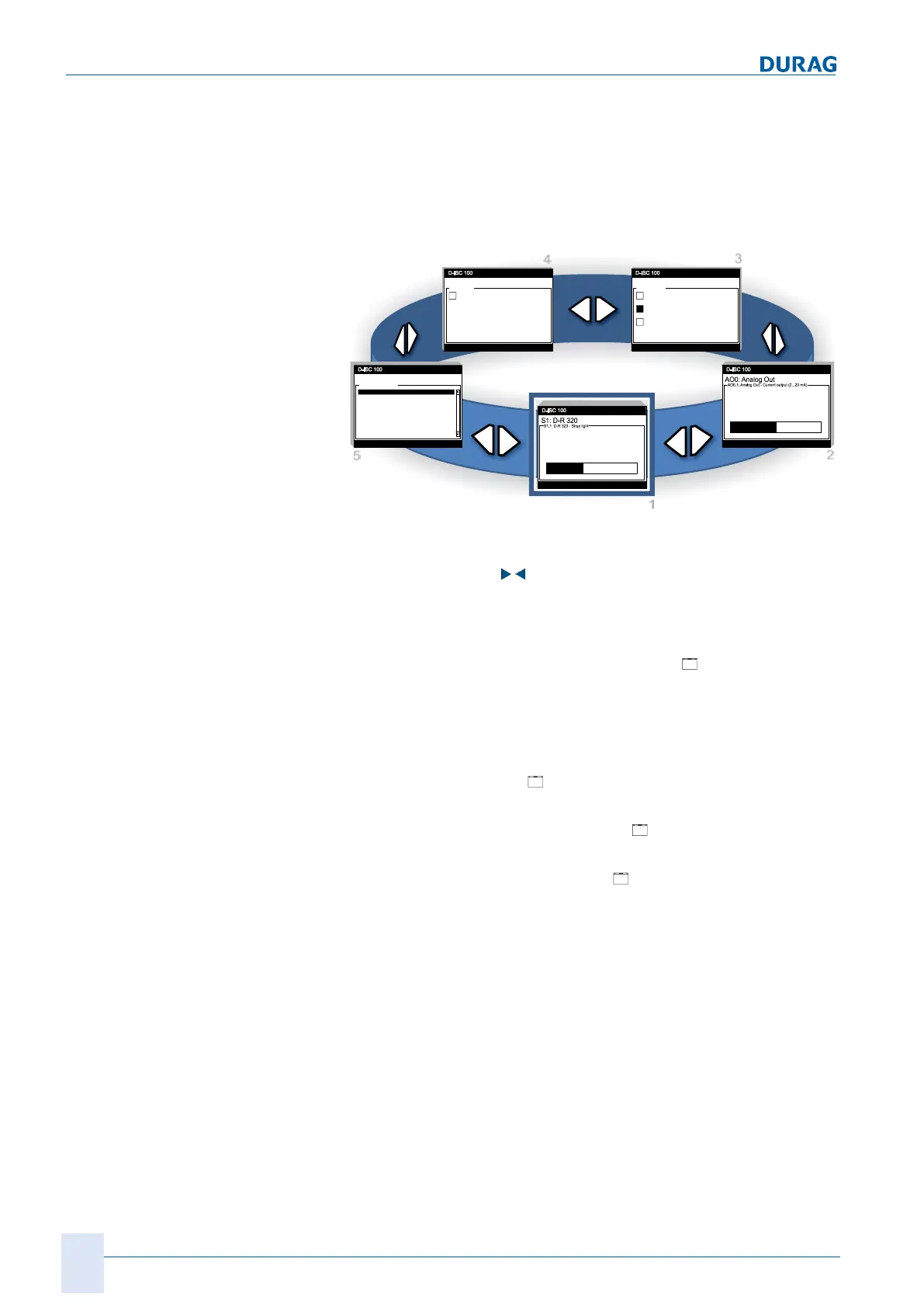
Fig.8.3: Measured value and status displays (display loop)
The two arrow keys ( ) can be used to scroll through the con-
figured measurement or status displays.
Example display:
In the example from Fig.8.3, a dust concentration measuring in-
strument D−R320 is connected to the Universal control unit. The
following displays could be configured in the
["Measurement
display after system start"]:
1. Measurement from the dust concentration measuring instru-
ment D−R320 (Fig.8.3: -1-). The graphic depiction of the
value is also shown in this display (configuration: bar graph).
2. Current output value
AO0: Analogue out] (Fig.8.3: -2-),
also with graphic depiction.
3. Configuration of the digital outputs
DO0:Digital out]. This
shows the relay assignment (Fig.8.3: -3-).
4. Configuration of the digital input
DI0:Digital in] (not as-
signed in this example) (Fig.8.3: -4-). This display could
mean that a control room could initiate a maintenance cycle
at a sensor, for example.
5. Device status for the overall system (D:) and for each indi-
vidual measurement channel of a sensor (S:) (Fig.8.3: -5-).
If several sensors are connected to the D‑ISC100, these dis-
plays are repeated for each connected sensor. Each sensor and
each sensor display can be configured individually in its own
menu.
 Loading...