30 | www.eddy.com
Using Reddy with Sharck Probes
Tangential Eddy Current Array Technology
TECA’s coil arrangement and tangential operation mode allow obtaining a particular eddy current signal
for surface-breaking cracks in carbon steel. As illustrated below, drivers induce eddy currents owing
mainly perpendicularly to the scan direction. When the eddy currents encounter longitudinal cracking,
they tend to move around it by diving underneath or around the extremities.
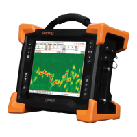
Figure 5–3 Simplied TECA working principles
The main characteristics of TECA signals are:
• Almost at liftoff signal
• Crack-like indications approximately 90° relative to the liftoff signal
• All crack-like indications feature the same phase shift
• Vertical signal amplitude linked to the defect depth (see gures below)
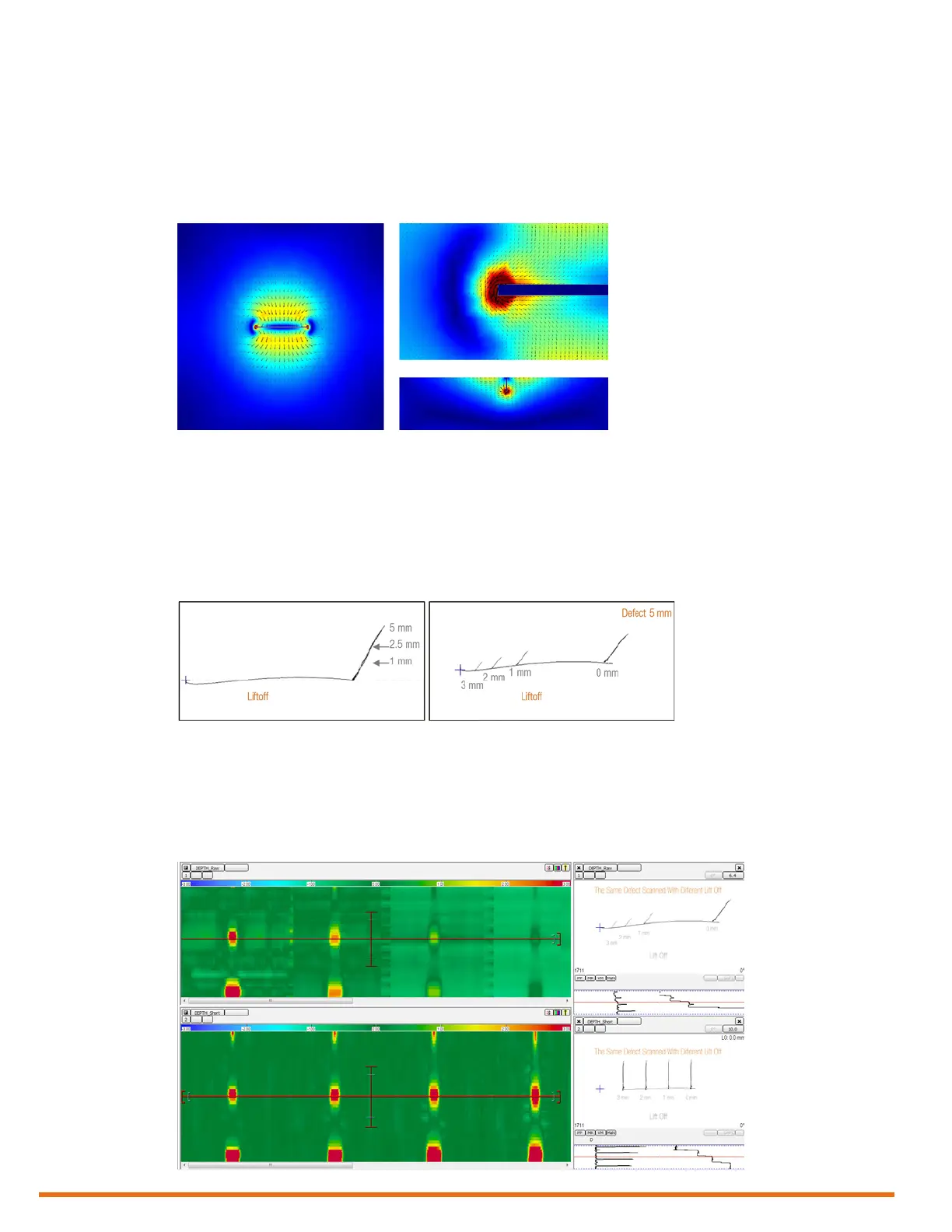
Figure 5–4 Typical signal signature
As the vertical signal amplitude is impacted by liftoff, the dynamic compensation process is designed to
overcome any sizing and visualization issues. As illustrated above, any given defect’s vertical signal
component can be reduced by a factor of 2 or 3 (or more) when there is signicant liftoff. However,
because the coil design allows monitoring liftoff, it can be measured and the defect signal can be adjusted
accordingly (see gure below).
Figure 5–5 Effects of compensation to liftoff on detected 5 mm deep defect with 0, 1, 2 mm liftoffs