| 45
Using Reddy with Sharck Probes
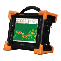
Figure 5–35 Report tab
• An axial crack-like indication is typically set to a phase of approximately 90° in the Short and Long
impedance places, and 135° phase in the Raw impedance plane.
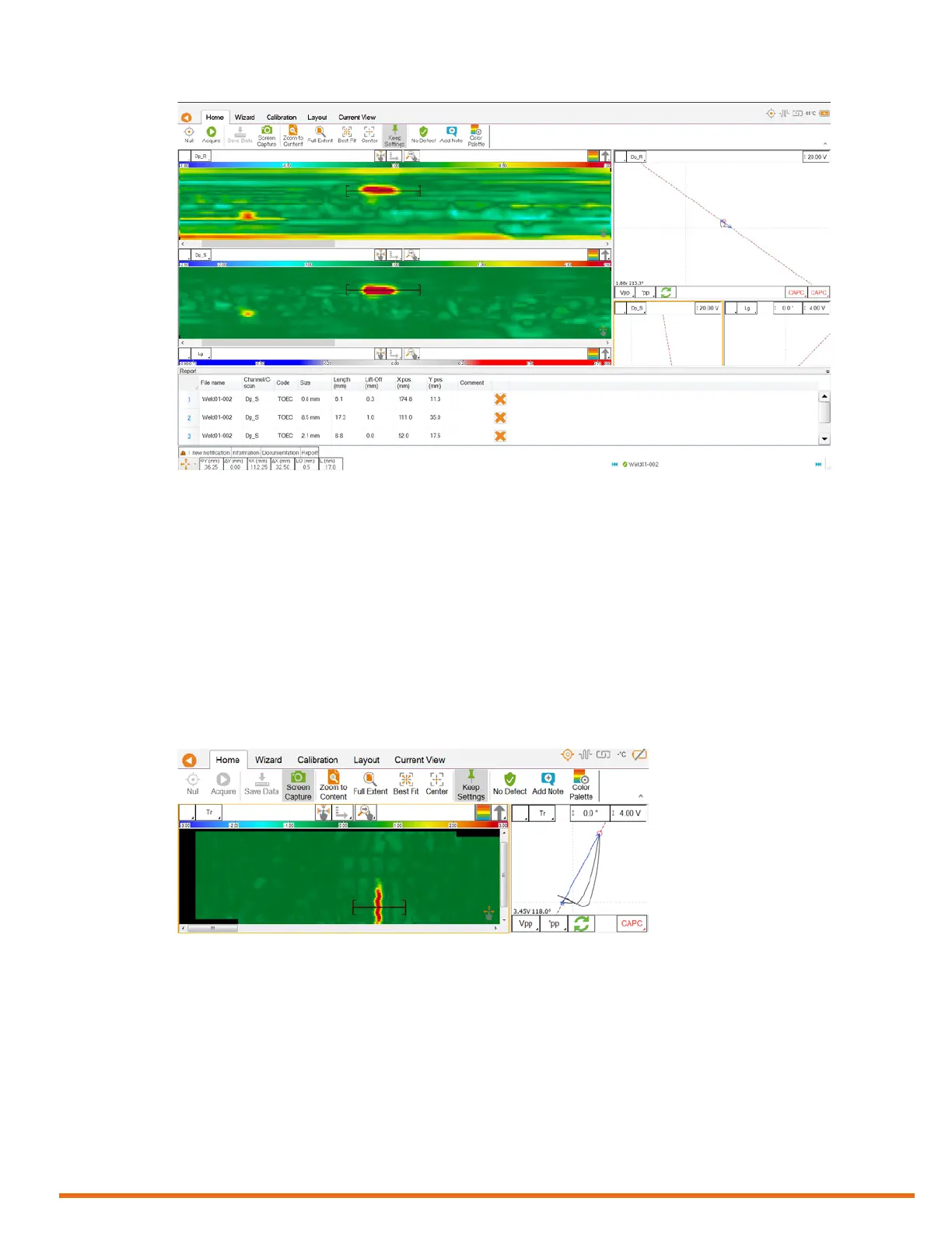
• A transverse crack-like indication is typically set to a phase approximately 45° in the Transverse
impedance plane. Generally, the length signals of such defects have a color opposite that of axial
cracks (red-blue instead of blue-red, see Figure 41).
• Those values can be altered by geometrical features and/or permeability variations.
• A differential signal appearing in the Length impedance plane with a mostly horizontal phase
(generally no bright spot in the Depth C-scans) can typically be considered a geometrical effect
from the weld, such as excess metal, undercut, etc.
• Size defects shorter than 25 mm (1 in) with the Depth Short C-scan. Size defects longer than 25 mm
(1 in) with the Depth Long C-scan.
Figure 5–36 Transverse C-scan