40 | www.eddy.com
Using Reddy with Sharck Probes
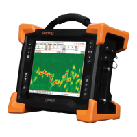
Figure 5–25 Sharck probe on carbon steel weld
5. On Reddy’s keypad, press the Start/Stop acquisition button (see page 3).
Alternatively, in the front stage view, on the Home or Calibration ribbon, tap Acquire.
Note
To ensure that the entire weld cap is covered by the probe’s ngers, whenever possible, position the
center of the probe’s active area on the centerline of the weld. Depending on the width of the weld
crown and the welding process, the probe may also cover all or part of the heat-affected zone (HAZ).
6. Placing appropriate pressure on the probe, move it longitudinally along the weld.
Note
The maximum speed is 200 mm/s (6 in/s) for the small (W028) and medium (W053) Sharck probes.
7. When scanning is complete, on Reddy’s keypad, press the Start/Stop acquisition button (see page
3.
Alternatively, in the front stage view, on the Home or Calibration ribbon, tap Stop.
Notes
• To maintain data les at a reasonable size and facilitate analysis, when inspecting very long welds,
we recommend that you divide your inspection into several appropriately short acquisitions (e.g.
less than 3 m (10 ft)).
• Balance the probe regularly between scans on the plastic portion of Eddy’s normalization plate
(REFPL-CAL-SHARCK-AAL-LG) to avoid any signal drift.
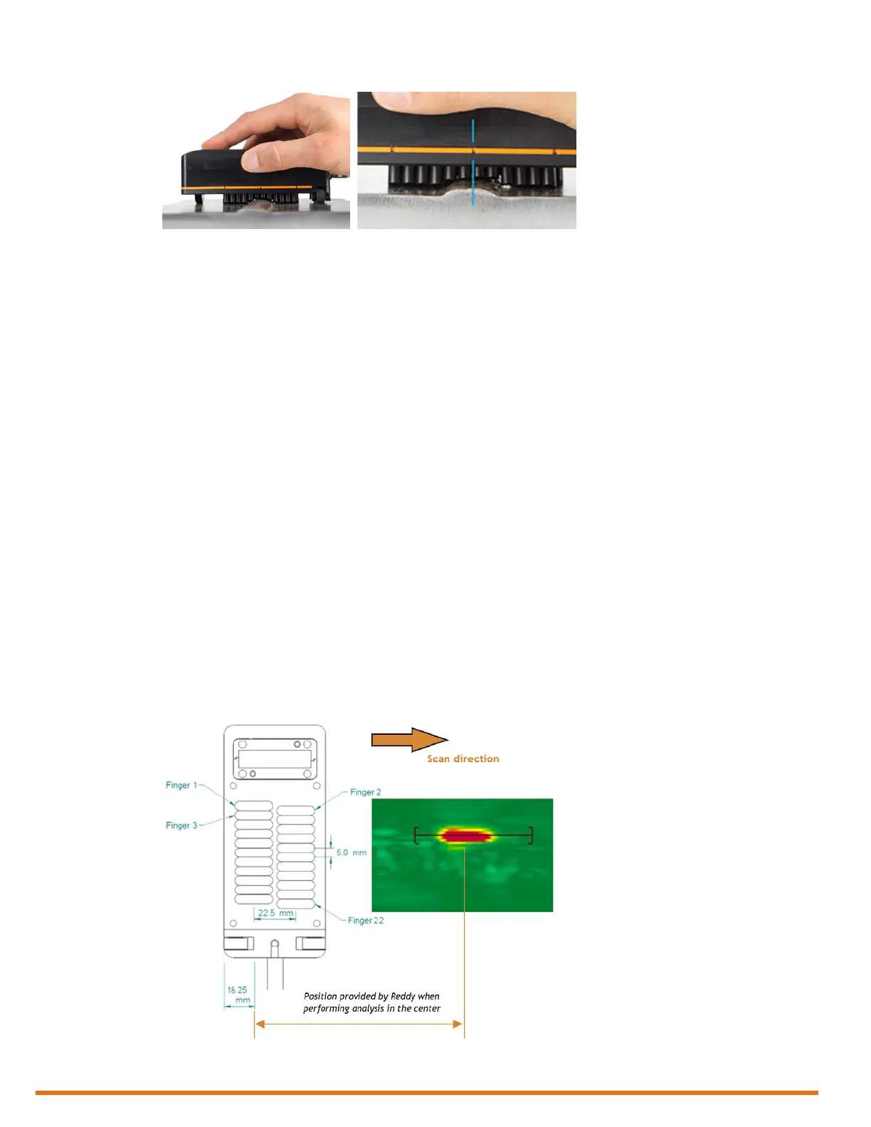
• Data is positioned according to the origin (0,0) illustrated below. This is the top view of the
probe (transparency). Along the scanning axis, the origin is 38.75 mm (1.53 in) from the front of
the probe’s casing (the front being the edge of the casing closest to the scan direction).
Figure 5–26 Probe origin and defect positioning along the scanning axis (probe shown top view)
• Data simultaneously appears on the Reddy display during acquisition and some of the functions
of the Home and Calibration ribbons are disabled.