2-
External Features
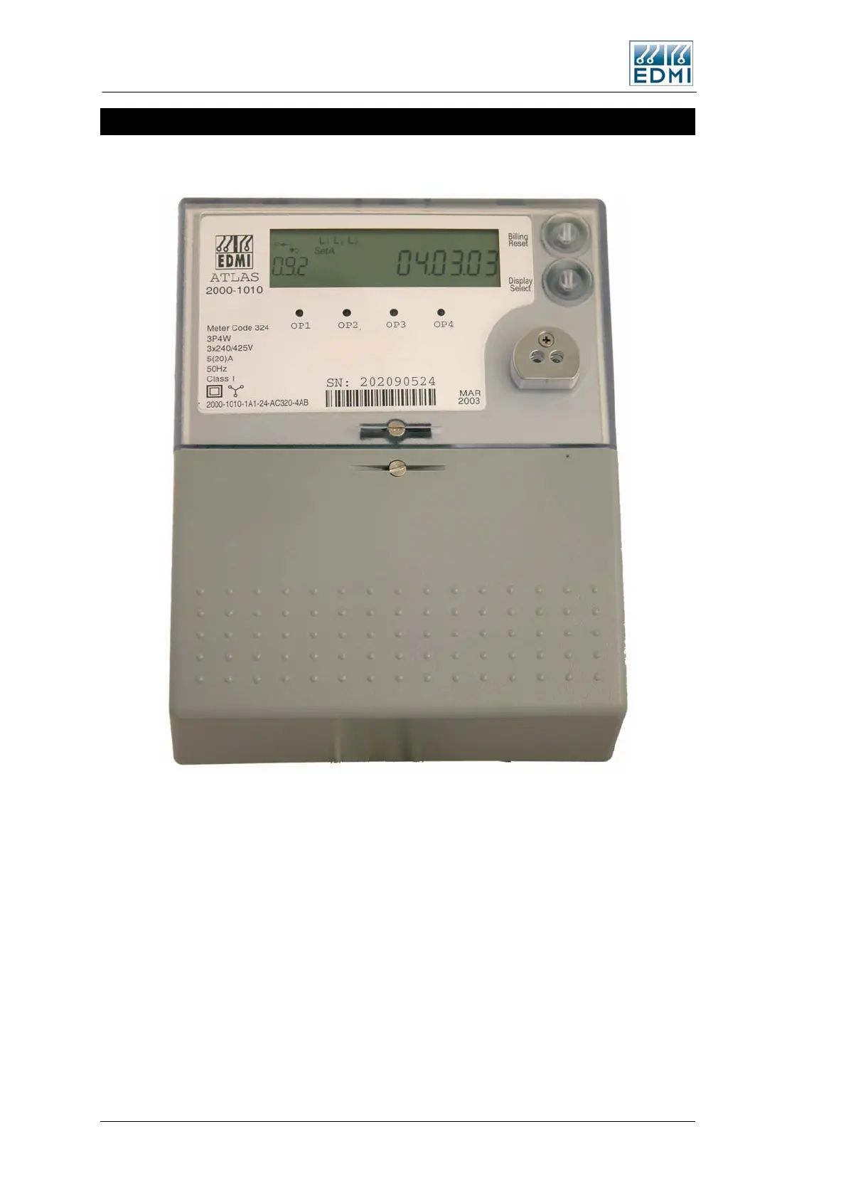
Figure 2-4 shows a view of the front of the meter (the specifics of your label will vary).
• Figure 2-4 Front view of the meter with terminal cover fitted
The major parts visible in Figure 2-4 include:
• The LCD display.
• A Select button for cycling the display (bottom push button).
• A sealable Billing Reset button (optional) to initiate a manual billing reset (top push
button).
• Four pulsing LEDs for energy indication (PO1 – PO4) which overlap the first 4
outputs. The special I/O variant has 2 LED’s (PO1, PO2), the UPS variant has 1
LED (PO1) – in these variants the LED’s are independent of the outputs.
• A FLAG or ANSI port for local connection.
2-4 EDMI Atlas Hardware Reference Manual
 Loading...
