6-1
RS-232
The RS-232 port on the meter uses an RJ45 connector, which complies with the RS-
232D standard. To connect to a modem, use a modem with an RJ45 connector, or use
an RJ45 to DB9 connector adapter. RTS/CTS hardware handshaking is not supported.
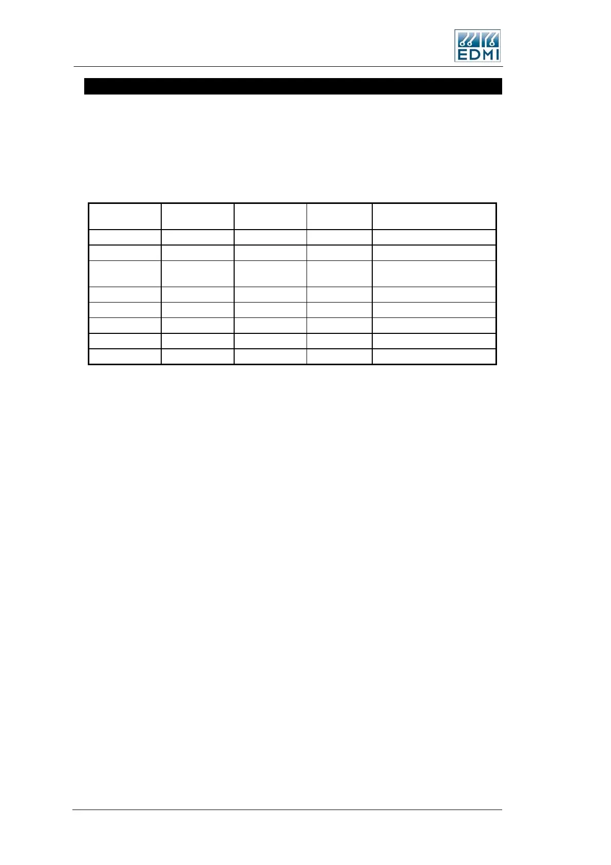
See Table 6-3 for connection details of TB10. Pin 1 of the RJ45 is on the right hand
side.
RS232D RJ45
From Meter
RS232C DB9
To Modem
RS232C DB9
To PC (Null)
Description Full Name
TB10-1 * (9) (9) +14 +14V,3.6W output
TB10-2 Not Connected
TB10-3 4 1 DTR
Data Terminal Ready
(from meter)
TB10-4 5 5 GND Ground
TB10-5 2 3 RX Receive Data (to meter)
TB10-6 3 2 TX Transmit Data (from meter)
TB10-7 RX2 Receive Data–SCADA port
TB10-8 TX2 Transmit Data-SCADA port
• Table 6-3 RS-232 connections
* TB10-1 is connected to a +14V power source from the meter, which is designed to
power an external GSM modem. Other options are also available, contact EDMI for
more details. Some early meters may have been built with a 2W limit – check with
EDMI if you have a concern.
See Figure 6-4 and Figure 6-5 for the location of the RJ45 connector. It is designated as
TB10.
RX2 and TX2 are only present if the port is a dual RS232 port.
When the SCADA port is on TB9, the connections are as per Table 6-3 except that
TB10-3, TB10-7, and TB10-8 are not connected.
6-12 EDMI Atlas Hardware Reference Manual
 Loading...
