Under the Terminal Cover
2-
The Mk10 Meter 2-5
Beneath the terminal cover (accessible by removing the sealable screw on the top
middle of terminal cover) is the terminal block for voltage and current, connectors for
the pulsing inputs and outputs (optional), the optional RS-232 or RS-485 interface, and
the optional external battery
The sealable screws have 2.15mm diameter holes to accommodate standard sealing
wire.
Under the Terminal Cover
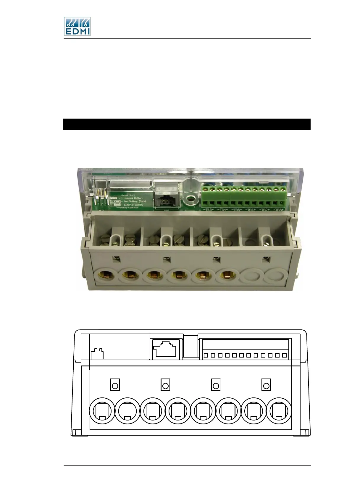
Most of the connections to the meter occur under the terminal cover. Figure 2-5 shows
the terminals available on a standard I/O variant 2 input / 4 output / RS-232 / CT
connected meter.
• Figure 2-5 Under the terminal cover of the meter
Diagrammatically, this is shown in Figure 2-6 with the terminal block numbering.
Battery
Connector
JP3
TB1
++ ++++-- ----
TB3TB4TB5TB6TB7TB8
TB2
1 3 4 6 8 10 12 14
25913
• Figure 2-6 Terminal block diagram
 Loading...
