Under the Terminal Cover
6-
TB1
TB2 TB3 TB4 TB5
TB9 TB10
1346
10 12 14
2591113
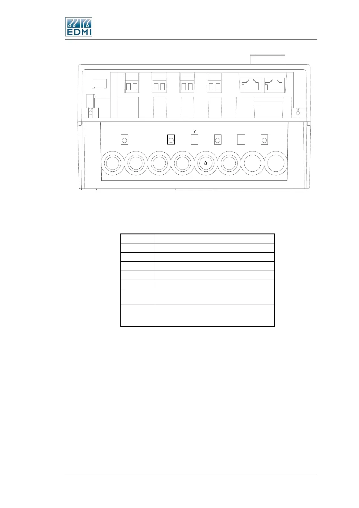
• Figure 6-5 Terminal block diagram
Table 6-1 lists the terminal block connections.
Terminal Description
TB1 Voltage and current inputs.
TB2 Input PI3 or Output PO3.
TB3 Input PI4 or Output PO4.
TB4 Input PI5 or Output PO5.
TB5 Input PI6 or Output PO6.
TB9
Second RJ45 connector for some
communication options.
TB10
RJ45 connector which is hardware configured
to either RS485 or RS232, or a 5 way terminal
block for RS485.
• Table 6-1 Terminal block connections
The Mk10E Meter 6-5
 Loading...