4-
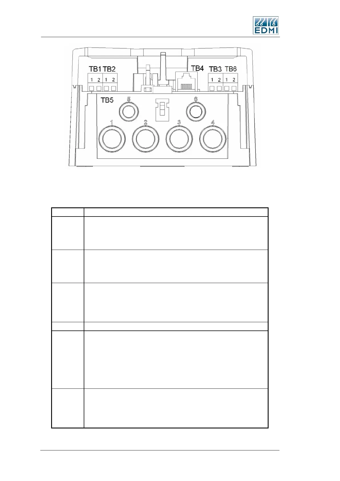
• Figure 4-6 Terminal block diagram
Table 4-1 lists the terminal block connections.
Terminal Description
TB1 Input PI1 or output PO1
SØ Output or 240V/110V/48V/12V/5V Input or Active Input
TB1-1 Input /Output PI1 or PO1
TB1-2 Common for Input/Output #1
TB2 Input PI1 & PI2
SØ Output or 240V/110V/48V/12V/5V Input or Active Input
TB2-1 Input /Output PI2 or PO2
TB2-2 Common for Input/Output #2
TB3 Input PI5 & PI5
SØ Output or 240V/110V/48V/12V/5V Input or Active Input or 2A,240V Relay
or BOSFET output
TB3-1 Input /Output PI5 or PO5
TB3-2 Common for Input/Output #5
TB4 RJ45 connector which is factory fitted with 1 or 2 RS232 ports.
TB5 Voltage and current inputs.
TB5-1 Incoming Active
TB5-2 Incoming Neutral
TB5-3 Outgoing Neutral
TB5-4 Outgoing Active L1
TB5-5 Additional Load #2 L3
TB5-6 Additional Load #1 L2
TB6 Input PI6 & PI6
SØ Output or 240V/110V/48V/12V/5V Input or Active Input or 2A,240V Relay
or BOSFET output
TB6-1 Input /Output PI6 or PO6
TB6-2 Common for Input/Output #6
• Table 4-1 Terminal block connections
4-6 EDMI Atlas Hardware Reference Manual
 Loading...