Connections in Detail
2-1
Mk10A Serial Port Configurations
The Mk10A meter has an option of one or two RS-232 ports, which can be arranged in
a number of configurations with an RS485 port. The two ports are called Modem and
SCADA. The possible options are listed in Table 2-9, which lines up with the order
code options (Rev 001).
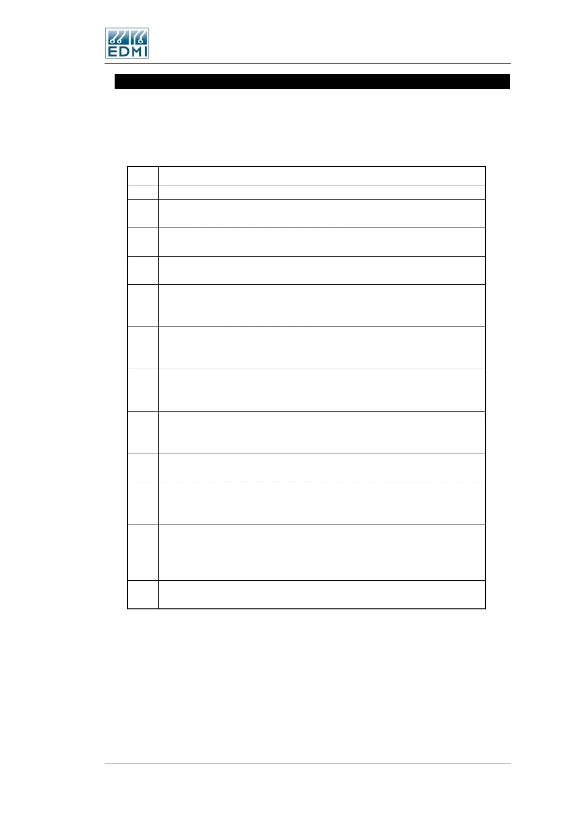
Type Port Arrangement
0 None
1
Modem: RS232 (RJ45 TB1, with DTR), no modem power
Basic RS232 port operation
2
SCADA:RS485 4-wire (2xRJ45 , TB9 &TB1), no modem power
Basic 4-wire 485 operation, two identical RJ45’s to allow easy daisy chaining
5
Modem: RS232 (RJ45 TB1, with DTR); with modem power
Basic modem operation, with modem power
7
Modem: RS232 (RJ45 TB1); SCADA: RS232 (RJ45 TB1, pins 7&8);
with modem power
Two RS232 ports on the one RJ45.
9
Modem: RS232 (RJ45 TB1); SCADA: RS232 (Slave RJ45 TB9, pins 5&6);
with modem power
Two RS232 ports, each on their own RJ45.
G
Modem: RS232 (RJ45 TB9); SCADA: RS485 4-wire (Slave RJ45 TB1);
with modem power
RS232 port on one RJ45, and a 4-wire RS485 port on the second RJ45
S
Modem: RS232 (RJ45 TB9); SCADA: RS485 2-wire (Screw Terminal TB1);
with modem power
RS232 port, and a 2-wire RS485 port on a 3-way terminal block
T
SCADA: RS485 4-wire (2x RJ45, TB9 &TB1); with modem power
Basic 4-wire 485 operation, two identical RJ45’s to allow easy daisy chaining
U
Modem: RS232 (RJ45 TB1); SCADA: RS485 2-wire (RJ45 TB1, pins 7&8);
with modem power
RS232 port, with a 2-wire RS485 port on the same RJ45 connector.
V
Modem: RS232 (RJ45 TB1); SCADA: RS485 2-wire (RJ45 TB1, pins 7&8 plus
Slave RJ45 TB9, pins 7&8); with modem power
RS232 port, with a 2-wire RS485 port on the same RJ45 connector, and a second
connector. Useful for master/slave
W
SCADA: RS485 2-wire (Screw Terminals TB1)
Basic 2-wire RS485 on a 3-way terminal block
• Table 2-9 Mk10A Serial port options
Where only one RJ45 is fitted it is TB1 that is fitted. TB1 is the right hand RJ45 and
TB9 is the left hand RJ45 (Mk10A only).
Type ‘V’ is particularly useful for master slave arrangements using identical build
meters. To share a modem between several meters, a modem is plugged into TB1 of the
‘master’ designated meter, using a cable that omits pins 7&8. A normal ‘all wires’
patch cable can then be used to connect TB9 to TB1 of the next meter, and the same
TB9 to TB1 connection can be continued between all the meters. Note that normally
The Mk10 Meter 2-17
 Loading...