External Features
3-
External Features
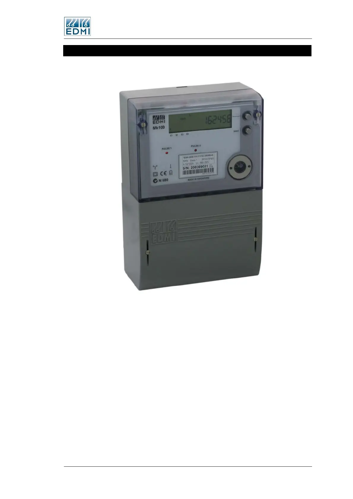
Figure 3-3 shows a view of the front of the meter (the specifics of your label will vary).
• Figure 3-3 Front view of the meter with terminal cover fitted
The major parts visible in Figure 3-3 include:
• The LCD display.
• A Select button for cycling the display (bottom push button).
• A sealable Billing Reset or Reconnect button (optional) to initiate a manual billing
reset (top push button).
• Two pulsing LEDs for energy indication (PO1 and PO2).
• A FLAG or ANSI port for local connection.
Beneath the terminal cover (accessible by removing the two sealable screws on the top
of the terminal cover) is the terminal block for voltage and current, connectors for the
pulsing inputs and outputs (optional), and the optional RS-232 or RS-485 interface.
The Mk10D Meter 3-3
 Loading...