5-1
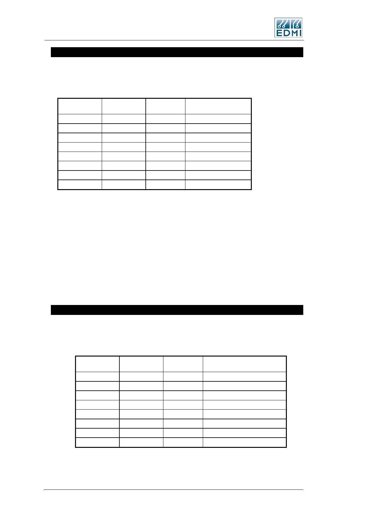
RS-485 Passive
The RS-485 port on the meter has the factory option of either an RJ45, or a 4 way
terminal block. Table 5-10 lists the connections. Pin 1 of the RJ45 is on the right hand
side. Pin 1 of the terminal block is on the left hand side.
RJ45
Terminal
Block
Description Full Name
TB4-3 TB4-2 TX+ (A) Transmit +
TB4-6 TB4-4 TX- (B) Transmit -
TB4-8 TB4-2 RX+ (A) Receive +
TB4-7 TB4-4 RX- (B) Receive -
TB4-4 TB4-3 GND Ground
TB4-5* TB4-1* +8V to +15V Port supply
TB4-1 Not Connected
TB4-2 Not Connected
• Table 5-10 RS-485 connections
*This terminal must be connected to an external power supply in the range of +8V to
+15V, with a capacity to supply 100mA (this is to deal with a shorted bus - normal
operating current is far lower).
Transmit refers to transmitting data from the meter. When a terminal block is used the
port operates in 2 wire mode. When an RJ45 is used the port operates in 4 wire mode.
To operate the meter in two wire mode, simply wire TX- to RX- and TX+ to RX+.
See Figure 5-8 and Figure 5-9 for the location of the connector, designated as TB4.
RS-485 Active
The RS-485 port on the meter has the factory option of either an RJ45, or a 2 way
terminal block. Table 5-11 lists the connections. Pin 1 of the RJ45 is on the right hand
side). Pin 1 of the terminal block is on the left hand side.
RJ45
Terminal
Block
Description Full Name
TB3-1 TX2 Transmit Data–SCADA port
TB3-2 RX2 Receive Data-SCADA port
TB3-3 TB3-1 TX+ (A) Transmit +
TB3-4 GND Ground
TB3-5* +12 +12V,200mA output
TB3-6 TB3-2 TX- (B) Transmit Data
TB3-7 TB3-2 RX- (B) Receive -
TB3-8 TB3-1 RX+ (A) Receive +
• Table 5-11 RS-485 connections
5-14 EDMI Atlas Hardware Reference Manual
 Loading...