External Features
6-
6. Insert the remaining two screws (meter base, under the terminal cover) to hold the
meter securely.
External Features
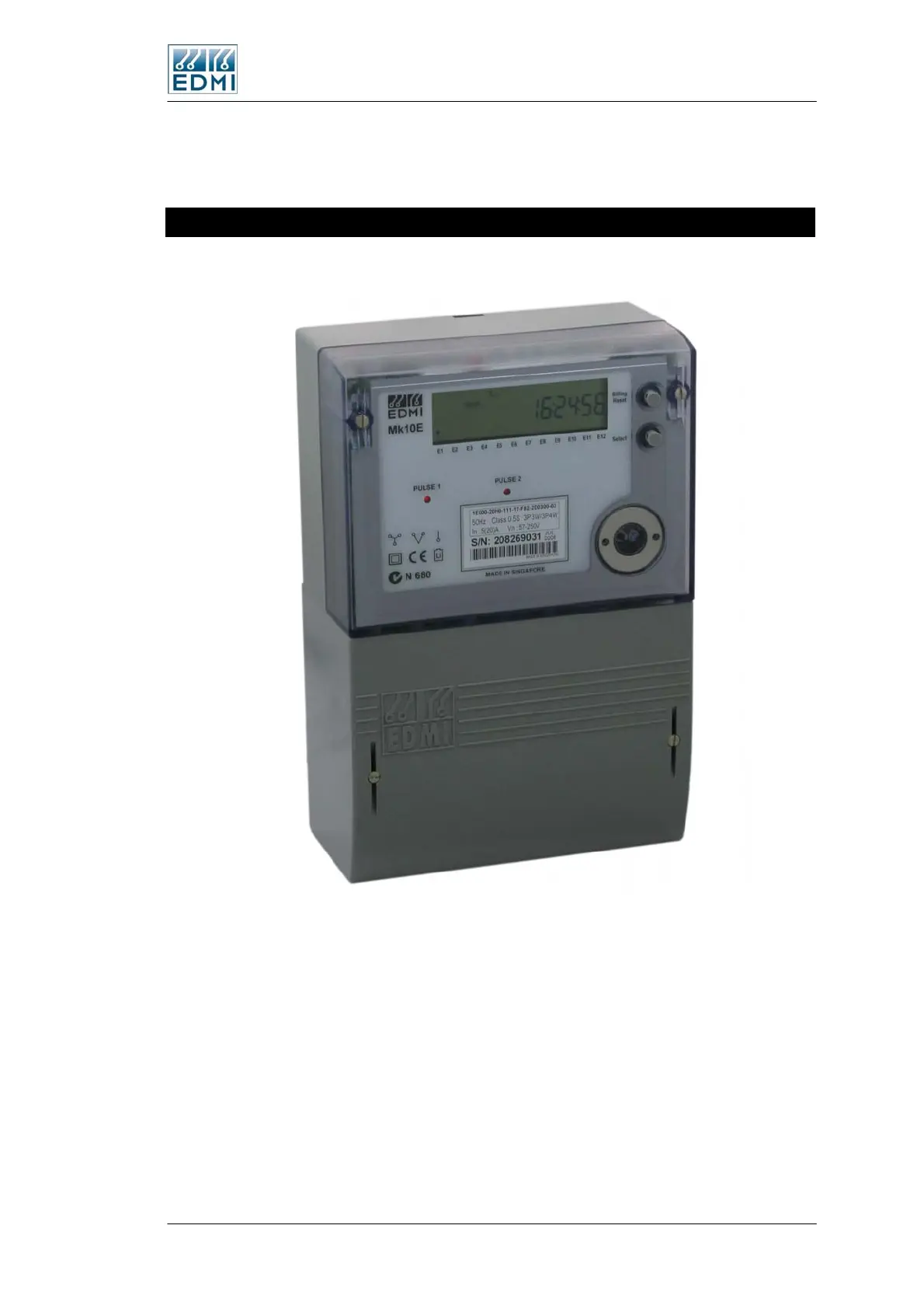
Figure 6-3 shows a view of the front of the meter (the specifics of your label will vary).
• Figure 6-3 Front view of the meter with terminal cover fitted
The major parts visible in Figure 3-3 include:
• The LCD display.
• A Select button for cycling the display (bottom push button).
• A sealable Billing Reset or Reconnect button (optional) to initiate a manual billing
reset (top push button).
• Two pulsing LEDs for energy indication (PO1 and PO2).
• A FLAG or ANSI port for local connection.
The Mk10E Meter 6-3
 Loading...
