Under the Terminal Cover
5-
Terminal Description
TB2 TB2-1 PI1/PO1 SØ Output or 240V/110V/48V/12V/5V Input
TB2-2 PI1/PO1 SØ Output or 240V/110V/48V/12V/5V Input
TB2-3 Common for PI1/PO1 and PI2/PO2
TB3 TB3-1 PI5/PO5 SØ Output or 240V/110V/48V/12V/5V Input
TB3-2 PI6/PO6 SØ Output or 240V/110V/48V/12V/5V Input
TB3-3 Common for PI5/PO5 and PI6/PO6
TB4 Nothing Fitted
• Table 5-6 Terminal block connections - PLC no relay
Terminal Description
TB2 TB2-1 PI1/PO1 SØ Output or 240V/110V/48V/12V/5V Input
TB2-2 PI2/PO2 SØ Output or 240V/110V/48V/12V/5V Input
TB2-3 Common for PI1/PO1 and PI2/PO2
TB3 TB3-2 PI6/PO6 SØ Output or 240V/110V/48V/12V/5V Input
TB3-3 Common for PI6/PO6
TB4 TB4-1 PO5 240V, 2A Relay output
TB4-2 Common for PO5
• Table 5-7 Terminal block connections - PLC with relay
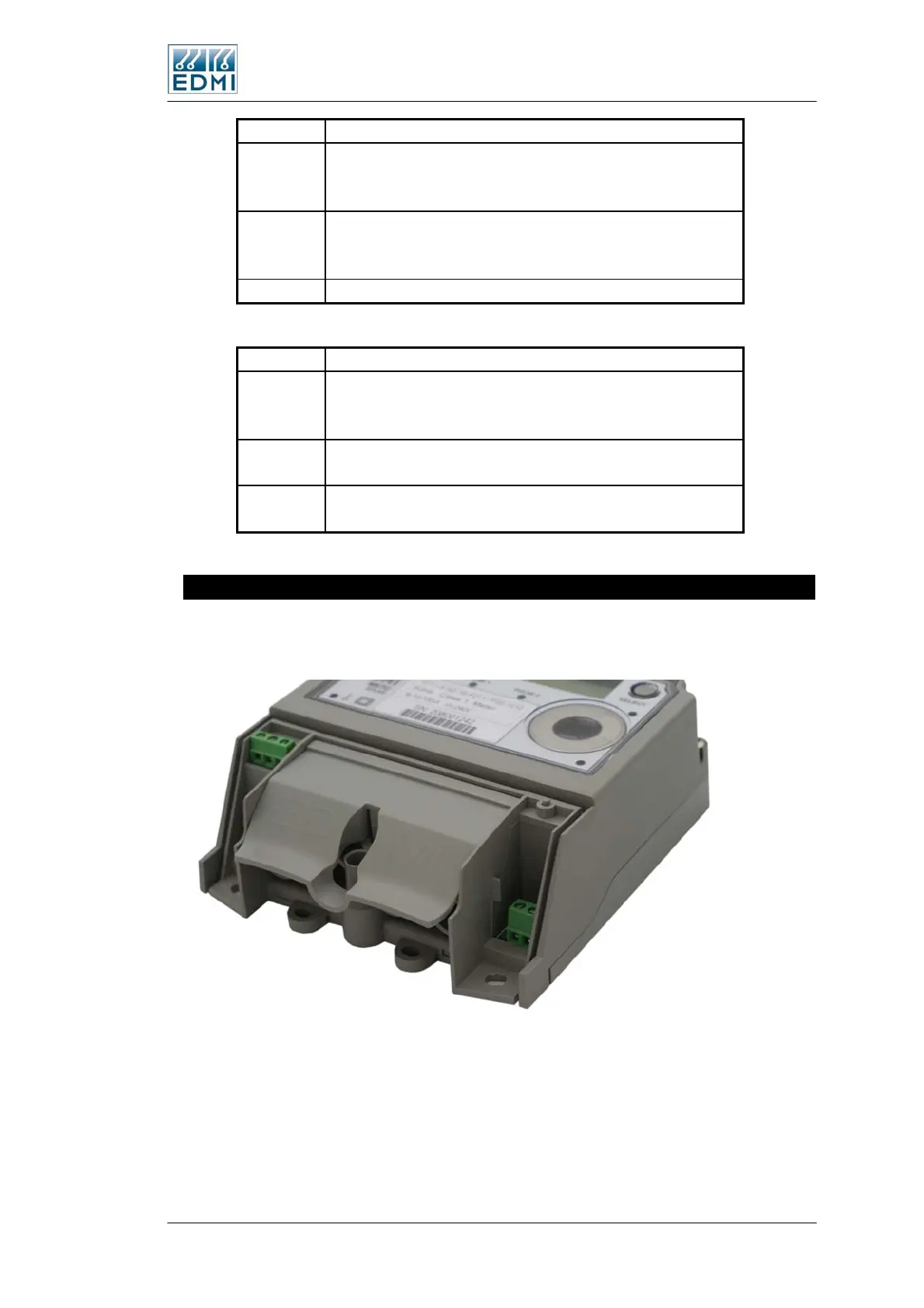
Finger Guard
A finger guard may be fitted over the TB1 terminal screws. This can help prevent
accidental contact with the supply voltage.
• Figure 5-11 The finger guard in place
The Mk7C Meter 5-9
 Loading...
