2-1
2-14 EDMI Atlas Hardware Reference Manual
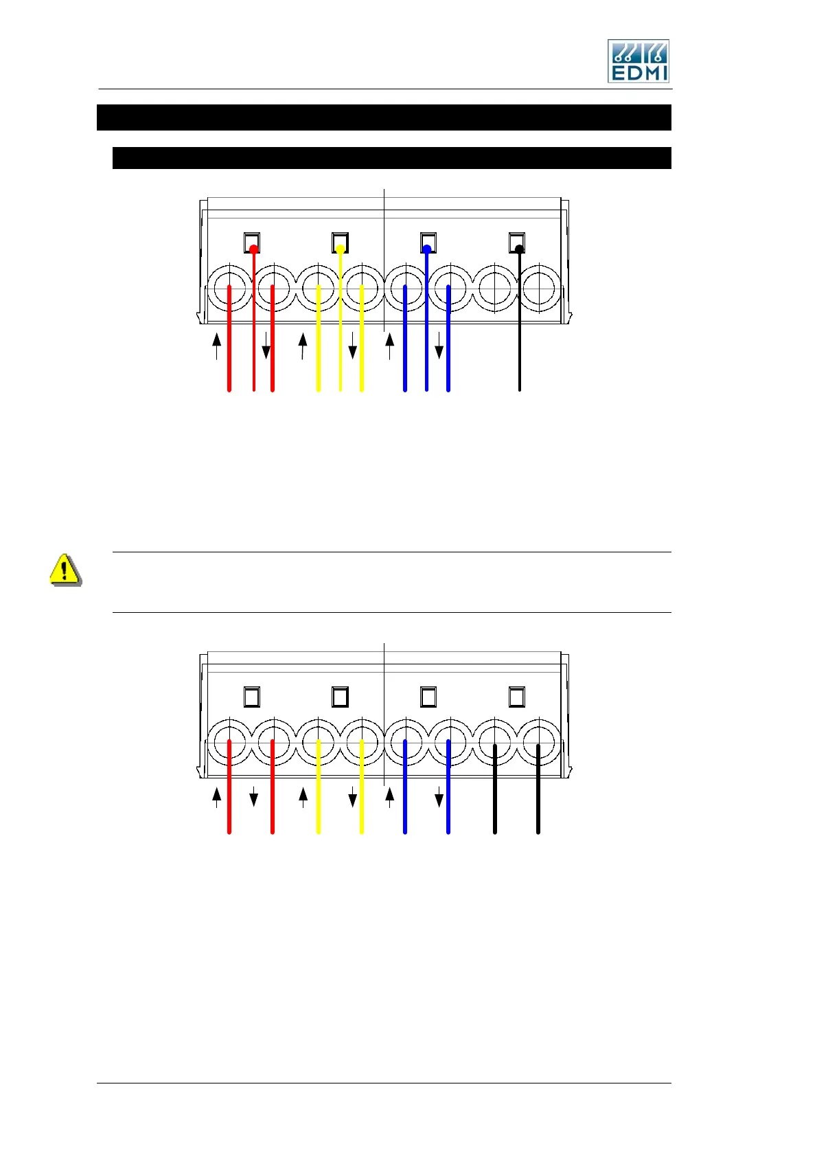
Connections in Detail
Current and Voltage
Phase A Phase B Phase C Neutral
Ia
Va
Ia
Ib
Vb
Ib
Ic
Vc
Ic
Vn
• Figure 2-18 TB2 CT and VT connections for 3 element
Figure 2-18 shows the connection methods in 3 element (4 wire) mode. The nominal
voltage input range is 240 VAC. The absolute limits are 140VAC to 290VAC. The
current range depends on the current range of the meter, and should be limited to Imax.
In 3 element mode (4 wire) the maximum line to neutral voltage is 290V and the
maximum line to line voltage is 500V. At any higher voltage the meter may not operate
correctly and damage may occur.
Ia
Ia
Ib
Ib
Ic
Ic
Phase A Phase B Phase C Neutral
• Figure 2-19 Connections for 3 element whole current
Figure 2-19 shows the connections for a whole current meter. The neutral connection
must be made, even if it is not connected to both 12 and 14. Whole current meters have
links connecting TB2 terminals 1 to 2, 4 to 5, 8 to 9, and 12 to 13 to 14. The links are
fitted under the main meter cover, discussed earlier in this chapter. The same maximum
voltage restrictions apply as for CT meters.
 Loading...
