Connections in Detail
2-19
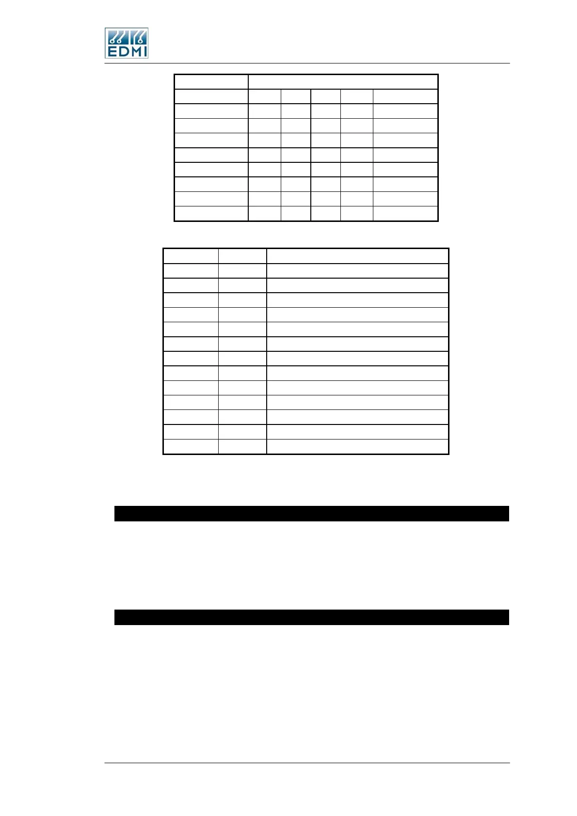
Port Type
Left Hand RJ45 2 9 G,S T V
TB9-1 +V +V +V +V
TB9-2
TB9-3 TX2+ TX2+
TB9-4 GND GND GND GND GND
TB9-5 RX2 RX
TB9-6 TX2- TX2 TX TX2-
TB9-7 RX2- RX2- Tx2-/Rx2- (B)
TB9-8 RX2+ RX2+ Tx2+/Rx2+(A)
• Table 2-12 Mk10A TB9 connections
Symbol Direction Description
+V Output External Modem supply: 12-20 VDC at 3.6W
GND Output Ground for all signals and supply
TX Output RS232 Transmit
RX Input RS232 Receive
DTR Output RS232 Data Terminal Ready
CD Input RS232 Carrier Detect
TX+ Output 4-wire RS485 Transmit + (A)
TX- Output 4-wire RS485 Transmit - (B)
RX+ Input 4-wire RS485 Receive + (A)
RX- Input 4-wire RS485 Receive - (B)
Tx+/Rx+(A) I/O 2-wire RS485 Transmit/Receive + (A)
Tx-/Rx- (B) I/O 2-wire RS485 Transmit/Receive - (B)
Blank No Connection
• Table 2-13 Symbol Descriptions
See Figure 2-8 for the location of the RJ45 connector. It is designated as TB1.
FLAG Port
The meter can have either a Flag Port or an ANSI Port. Use a standard FLAG (IEC1107
physical standard) read head to connect the meter to a PC.
Note that it has occasionally been found that some FLAG heads need to be rotated 180
degrees for them to work. If you have problems try this.
ANSI Port
The meter can have either Flag Port of ANSI Port. Standard Flag and ANSI read heads
should work with the meter. Please note that older EDMI ANSI read heads will not
work with the meter. To use a smart read head that can automatically switch polarity,
set the DTR line to be low – see Configure in the Site Properties section of the EziView
Basics chapter in the Atlas Software Reference Manual.
The Mk10 Meter 2-19
 Loading...
