Under the Terminal Cover
2-
Terminal Description
TB1
RJ45 connector which is hardware configured
to either RS485 or RS232, or a 5 way terminal
block for RS485.
TB2 Voltage and current inputs.
TB3 Active Input - PI3.
TB4 Active Input - PI4.
TB5 Active Input - PI5.
TB8 UPS Battery connector.
• Table 2-4 UPS Terminal block connections
All 3 inputs are active. Thus there is no isolation between TB1, TB3, TB4, and TB5.
All inputs and TB1 are isolated from the line (neutral) by 4kV. Note in some revisions
of the PCB show +/- indications opposite to the actual board. The right hand terminal of
each pair is the ground connection.
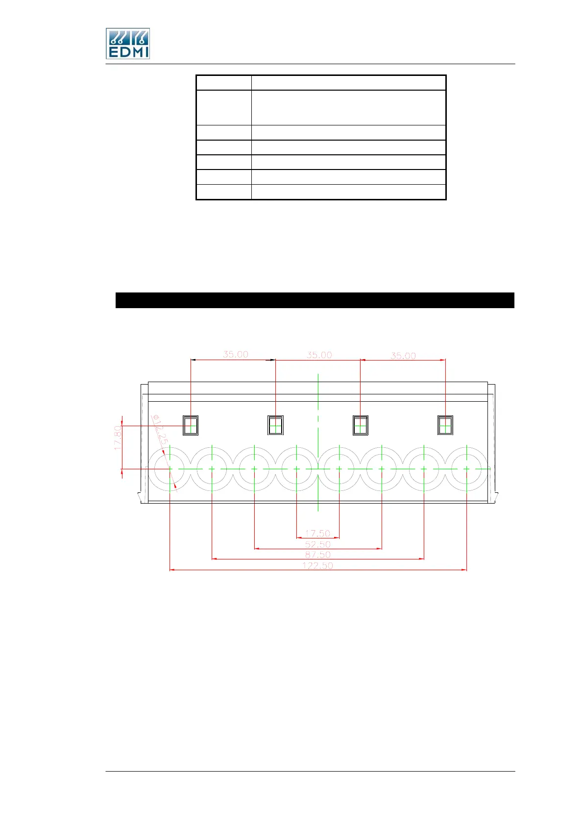
Terminal Spacing
Figure 2-10 gives the terminal spacing of TB2.
• Figure 2-10 TB2 terminal spacings
There are several styles of terminal in use – Table 2-5 summarises their inner
dimensions.
The Mk10 Meter 2-9
 Loading...
