3-
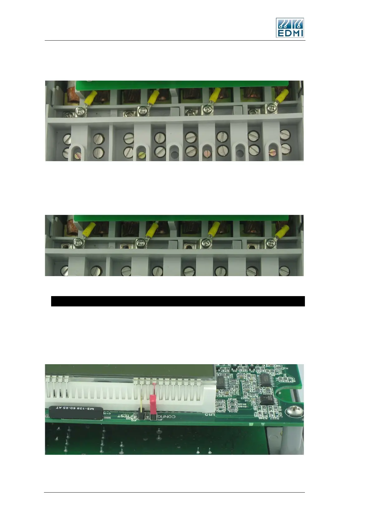
The second option has no external VT to CT links, so the meter lid must be removed to
change the links. Figure 3-11 shows the location of the links in this case, just above the
terminal block.
• Figure 3-11 Location of the CT to VT links.
To remove the link connections, remove the four screws and washers from the deeper
set of holes. This disconnects the links. Figure 3-12 shows the meter with the screws
removed.
• Figure 3-12 Meter with the CT to VT links disconnected by removing screws.
Config Jumper
The Config jumper offers a level of hardware security to the meter – the jumper needs to
be fitted to allow calibration and recovery of lost passwords. The jumper is located
under the meter lid, half way along the top of the meter above the LCD (Figure 3-13). A
jumper is fitted across the set of pins marked Config. The other set of pins marked FTest
are for factory use only.
• Figure 3-13 Location of the Config jumper
3-8 EDMI Atlas Hardware Reference Manual
 Loading...