Under the Terminal Cover
2-7
The Mk10 Meter 2-7
Terminal Description
TB1
RJ45 connector which is hardware configured
to either RS485 or RS232, or a 5 way terminal
block for RS485.
TB2 Voltage and current inputs.
TB3 I/O - PI3 or PO3.
TB4 I/O - PI4 or PO4.
TB5 I/O - PI5 or PO5.
TB6 I/O - PI6 or PO6.
• Table 2-2 Special I/O Terminal block connections
All 4 I/O can be either SØ Outputs, BOSFET Outputs or 240V/110V/48V/12V/5V
Inputs. PO3 and PO6 have the option of a 2A, 240V relay. TB4 and TB5 should not be
considered as isolated from each other (1mm creepage between them). Isolation of TB1
to TB3, TB3 to TB4 and TB5 to TB6 is 4kV (unless active inputs are fitted, in which
case there is no isolation between TB1 and the active inputs). All I/O are isolated from
the line (neutral) by 4kV.
Mk10A Variant
This variant has similar I/O options to the special I/O variant. Figure 2-8 shows the
terminal layout, and Table 2-3 lists the terminal block connections.
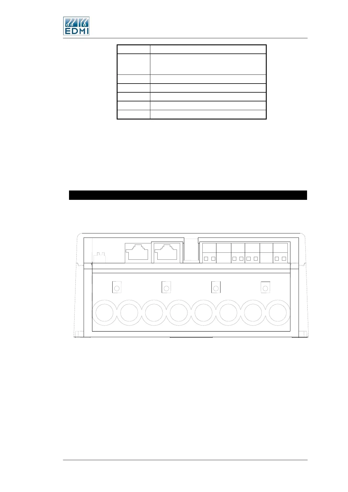
• Figure 2-8 Mk10A variant terminal block diagram
+ + + +
TB3 TB5 T B 6 T B 8
TB1
B a tte r y
C o nn e c t o r
J P 3
T B 2
1 3 4 6 8 10 1 2 1 4
2 5 9 1 3
TB9
 Loading...
